This thread has been locked.

If you have a related question, please click the "Ask a related question" button in the top right corner. The newly created question will be automatically linked to this question.

[参考译文] MSP430FR5987:MSP430FR5987 UART 配置问题:波特率19200、频率8MHz

Guru**** 1831610 points
Other Parts Discussed in Thread: MSP430FR5987
请注意,本文内容源自机器翻译,可能存在语法或其它翻译错误,仅供参考。如需获取准确内容,请参阅链接中的英语原文或自行翻译。

https://e2e.ti.com/support/microcontrollers/msp-low-power-microcontrollers-group/msp430/f/msp-low-power-microcontroller-forum/1414671/msp430fr5987-msp430fr5987-uart-configuration-problem-baud-rate-19200-frequency-8mhz

器件型号:MSP430FR5987

工具与软件:

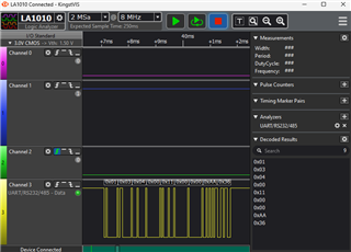
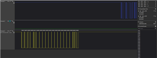
我将从 Modbus 系统中截取数据。 我可以使用逻辑分析仪看到该价值、但它没有出现串行终端。  

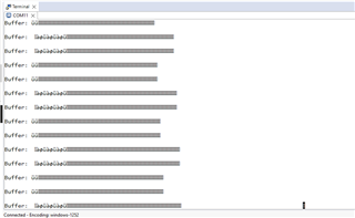
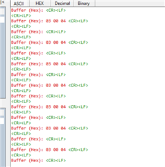
我尝试打印正常的字符串它正在工作,但缓冲区中的数据永远不会到串行终端?

请多多指教。 我所使用的芯片 MSP430FR5987已插入适用于特定项目的电路中。 Im 使用19200波特率、是否是在串行终端中未获取这些缓冲值的原因?

我 观看了 一个视频教程、其中提到如果我想使用高于9600的波特率、我必须 使用 USB 到 UART 转换器(FT232RL)。  

寻找您的宝贵建议和建议。

谢谢

  • 请注意,本文内容源自机器翻译,可能存在语法或其它翻译错误,仅供参考。如需获取准确内容,请参阅链接中的英语原文或自行翻译。

    某些通过 USB 连接具有"背面"串行通道的评估板对比特率确实有限制。 但尚不清楚这是否适用。 您还没有真正说明如何建立串行数据连接。

  • 请注意,本文内容源自机器翻译,可能存在语法或其它翻译错误,仅供参考。如需获取准确内容,请参阅链接中的英语原文或自行翻译。

    我不知道,这就是为什么张贴在这里。 我以前从未在19200波特率上工作过、但4800工作正常。

    #include

    #define BUFFER_SIZE 256 //用于保存捕获的 Modbus 帧的缓冲区大小
    #define TIMEOUT_THRESHOLD 14583 //在8MHz 时钟上超时19200毫秒

    volatile char bufferA[buffer_size];//保存捕获的 Modbus 帧的缓冲区的大小
    volatile char bufferB[buffer_size];// Modbus 数据的第二个缓冲区
    volatile char* activeBuffer = bufferA;//活动缓冲区指针(初始为 bufferA)
    Volatile char* sendBuffer = 0;//发送到主机的缓冲区

    volatile unsigned int bufferIndex = 0;//用于跟踪活动缓冲区中的缓冲区位置的索引
    volatile unsigned int modbusFrameComplete = 0;//指示帧结束的标志
    volatile unsigned int bufferReadyToSend = 0;//标志以指示缓冲区已准备好发送

    //此函数用于配置 UART 以进行 Modbus 通信(19200波特、8N1)
    void configureClocks (void)

    CSCTL0_H = CSKEY >> 8;//解锁 CS 寄存器
    CSCTL1 = DCOFSEL_3 | DCORSEL;//将 DCO 设置为8MHz
    CSCTL2 = SELS__DCOCLK;//设置 SMCLK = DCO
    CSCTL3 = DIVS__1;//将 SMCLK 分频器设置为1
    CSCTL0_H = 0;//锁定 CS 寄存器
    }


    // UART 函数用于传输单字节

    void uartTransmitChar (char c){
    while (! (UCA1IFG & UCTXIFG));//等待发送缓冲区为空
    UCA1TXBUF = c;//发送字符
    }


    // uart 函数以传输字符串
    void uartTransmitString (const char * str){
    while (*str){//循环通过字符串直到缓冲区为空
    uartTransmitChar(*str);//发送每个字符
    STR++;//移动到下一个字符
    }
    }

    // uart 函数以传输缓冲器的内容
    void uartTransmitBuffer (const char* buffer、unsigned int 长度){
    unsigned int i;
    uartTransmitString ("\r\n 缓冲区:");
    对于(i = 0;i < length;i++){
    uartTransmitChar (buffer[i]);//在缓冲区中发送每个字节
    }
    uartTransmitString ("\r\n");//缓冲区输出后添加新行
    }

    // UART 函数以两位十六进制值的形式传输单字节
    void uartTransmitHexByte (无符号字符字节){
    const char hexChars[]="0123456789ABCDEF";
    uartTransmitChar (hexChar[(byte >>4)& 0x0F]);//发送高半字节
    uartTransmitChar (hexChars[byte & 0x0F]);//发送低半字节
    }

    // uart 函数以十六进制形式传输缓冲器的内容
    void uartTransmitBufferHex (const char* buffer、unsigned int length){
    unsigned int i;
    uartTransmitString ("\r\n 缓冲区(十六进制):");
    对于(i = 0;i < length;i++){
    uartTransmitHexByte (buffer[i]);//以十六进制发送每个字节
    uartTransmitChar ('');//在字节之间添加空格
    }
    uartTransmitString ("\r\n");//缓冲区输出后添加新行
    }

    //此函数用于配置 UART

    空 configureUART()

    //设置 UART 配置:19200波特率、8个数据位、无奇偶校验、1个停止位
    UCA1CTL1 |= UCSWRST;//将 eUSCI 置于复位状态
    UCA1CTL1 |= UCSSEL_2;// SMCLK 作为时钟源

    UCA1BRW = 26;// 8MHz 时钟的波特率19200

    UCA1MCTLW =(0x54 << 8)|(0x00 << 4)| UCOS16;//调制 UCBRSx=0xD6、UCBRFx=0、过采样


    PM5CTL0 &=~μ A LOCKLPM5;//打开 I/O
    UCA1CTL1 &=~UCSWRST;//初始化 eUSCI
    UCA1IE |= UCRXIE;//启用 USCI_A1 RX 中断
    UCA1IE |= UCTXIE;

    }


    void UARTRxTx (void){
    /*
    //P3.4 (TXD)和 P3.5 (RXD)
    P3SEL0 |= BIT4 | BIT5;//为 UART 模式设置 P3.4 (TX)和 P3.5 (RX)(SEL0 = 1)
    P3SEL1 &=~(BIT4 | BIT5);//清除 SEL1中的 P3.3和 P3.4 (SEL1 = 0)
    */

    //设置端口
    P3SEL1 &=~BIT4;//清除 P3SEL1位4 (TXD)
    P3SEL0 |= BIT4;//设置 P3SEL0位4 (TXD)

    P3SEL1并且=~BIT5;//清除 P3SEL1的位5 (RXD)
    P3SEL0 |= BIT5;//设置 P3SEL0位5 (RXD)

    }

    //将 P3.0配置为输出以控制 LED
    void configureLED (void){
    P3DIR |= BIT0;//将 P3.0设置为输出(LED)
    P3OUT 并且=~BIT0;//开始时 LED 关闭
    }

    //切换连接到 P3.0的 LED
    void toggleLED (void){
    P3OUT ^= BIT0;//切换 P3.0 (LED)
    }

    //在接收模式下初始化 RS485收发器的示例函数
    void configureRS485 (){
    P3DIR |= BIT7;//将 RS485 DE (驱动器使能)引脚设置为输出
    P3OUT &=~BIT7;// DE = 0 (接收模式)

    P3DIR |= BIT3;//将 RS485 RE (接收使能)引脚设置为输出
    P3OUT 并且=~BIT3;// RE = 0 (接收模式)
    }

    void configureTimer (void){
    TA0CCTL0 = CCIE;//启用 Timer_A 捕捉/比较的中断
    TA0CCR0 = TIMEOUT_THRESHOLD;//设置超时的比较值(1.82ms)
    TA0CTL =tassel_2 + MC_0;//使用 SMCLK (8MHz)、开始停止计时器
    }

    void startTimer (void){
    TA0R = 0;//复位计时器计数器
    TA0CTL |= MC_1;//在向上计数模式下启动计时器
    }

    void stopTimer (void){

    TA0CTL &=~MC_1;//停止计时器
    }

    // Modbus 的 CRC16计算(多项式:0xA001)
    unsigned int calculateCRC16 (const char* data、unsigned int length){
    unsigned int CRC = 0xFFFF;//将 CRC 初始化为0xFFFF
    unsigned int i、j;

    对于(i = 0;i < length;i++){
    crc ^= data[i];//将字节异或到当前 CRC 值
    对于(j = 0;j < 8;j++){
    if (CRC & 0x0001){
    CRC >>=1;
    CRC ^= 0xA001;//应用多项式
    其他{
    CRC >>=1;
    }
    }
    }
    返回 CRC;
    }

    //接收 Modbus 数据的 ISR 示例
    #pragma VECTOR=USCI_A1_VECTOR
    _interrupt void USCI_A1_ISR (void){
    if (UCA1IFG & UCRXIFG){//检查是否已接收到数据
    char receivedByte = UCA1RXBUF;//读取接收到的数据

    //重置和启动计时器以进行超时检测
    stopTimer();
    startTimer();


    //如果有空间、则将接收到的字节存储在缓冲区中
    if (bufferIndex < buffer_size){
    activeBuffer[bufferIndex++]= receivedByte;
    }其他{
    //将缓冲器索引重置为1 (因为已存储字节)
    }

    }
    }

    #pragma vector=TIMER_A0_VECTOR
    _interrupt void timer_A0_ISR (void){
    //发生 Modbus 帧超时(检测到帧结束)
    stopTimer();

    //表示已捕获 Modbus 帧并已准备好进行处理的信号
    modbusFrameComplete = 1;

    //交换缓冲区:使当前缓冲区准备好发送并切换到下一个缓冲区
    sendBuffer = activeBuffer;//将 activeBuffer 分配给 sendBuffer
    bufferReadyToSend =1;//Flag to send buffer
    activeBuffer =(activeBuffer == bufferA)? bufferB:bufferA;
    bufferIndex = 0;//重置缓冲区索引
    }

    void main (void){
    WDTCTL = WDTPW | WDTHOLD;//停止看门狗计时器
    configureClocks();
    configureUART ();//初始化 UART
    UARTRxTx();
    configureRS485 ();//在接收模式下配置 RS485收发器
    configureTimer();


    __bis_SR_register (GIE);//启用全局中断
    while (1){
    //主循环:等待 Modbus 帧完成
    if (modbusFrameComplete){
    modbusFrameComplete= 0;//重置帧完成标志
    //切换 LED
    toggleLED();

    uartTransmitBuffer (sendBuffer、bufferIndex);////发送十六进制缓冲区内容
    bufferIndex = 0;//重置下一帧的缓冲区索引
    }
    }
    __bis_SR_register (LPM0_bits+GIE);//进入低功耗模式、等待中断
    }

  • 请注意,本文内容源自机器翻译,可能存在语法或其它翻译错误,仅供参考。如需获取准确内容,请参阅链接中的英语原文或自行翻译。

    UCA1IE |= UCTXIE;

    删除此行。 你的 ISR 不使用 UCTXIFG、所以程序将花费几乎全部的时间来完成 ISR、并且主程序不会取得任何进展。

  • 请注意,本文内容源自机器翻译,可能存在语法或其它翻译错误,仅供参考。如需获取准确内容,请参阅链接中的英语原文或自行翻译。

    删除了、但恐怕通过串行终端没有任何内容。 在这种情况下、您可以建议我吗?

  • 请注意,本文内容源自机器翻译,可能存在语法或其它翻译错误,仅供参考。如需获取准确内容,请参阅链接中的英语原文或自行翻译。

    TIMER_A0_ISR 设置  modbusFrameComplete = 1、但也设置 bufferIndex = 0、因此在主函数看到没有要发送的内容时(看起来似乎是)。

    对于这两种用途、我怀疑您需要两个不同的变量。

  • 请注意,本文内容源自机器翻译,可能存在语法或其它翻译错误,仅供参考。如需获取准确内容,请参阅链接中的英语原文或自行翻译。

    我想从 Modbus 捕获数据、即使我可以在逻辑分析仪中看到这些数据、并在附上它供您参考。  

  • 请注意,本文内容源自机器翻译,可能存在语法或其它翻译错误,仅供参考。如需获取准确内容,请参阅链接中的英语原文或自行翻译。

    CSCTL2 = SELS___DCOCLK;//设置 SMCLK = DCO

    我很确定这会设置 MCLK=LFXTCLK (或者可能是 VLOCLK)、确实是(!) 慢速。 这不会影响您的 UART、但它可能表现不佳。 请尝试改用:

    > CSCTL2 = SELS__DCOCLK|SELM__DCOCLK;//设置 SMCLK = MCLK = DCO

    或者根本不设置 CSCTL2。 (不过、请将 CSCTL3中的分频器设置为/1。)

  • 请注意,本文内容源自机器翻译,可能存在语法或其它翻译错误,仅供参考。如需获取准确内容,请参阅链接中的英语原文或自行翻译。

    因此、您可以使用逻辑分析仪看到数据、但无法在串行终端上看到。 这意味着您应该检查串行终端的连接和配置。

    虽然串行终端可以很好地处理可打印的 ASCII 字符、但这种不可打印的东西是一个非常不同的问题。

  • 请注意,本文内容源自机器翻译,可能存在语法或其它翻译错误,仅供参考。如需获取准确内容,请参阅链接中的英语原文或自行翻译。

    你为什么给 TransmitChar ()一个半字节? 它以字符/字节为单位工作。

    另外、请使用代码标签发布您的代码。

  • 请注意,本文内容源自机器翻译,可能存在语法或其它翻译错误,仅供参考。如需获取准确内容,请参阅链接中的英语原文或自行翻译。

    每个 nybble 转换成可打印的 ASCII。 这显然是 MODBUS 而不是 MODBUS RTU,这是二进制的。 尽管逻辑分析仪数据看起来是二进制的。

  • 请注意,本文内容源自机器翻译,可能存在语法或其它翻译错误,仅供参考。如需获取准确内容,请参阅链接中的英语原文或自行翻译。

    #include <msp430.h>
    
    #define BUFFER_SIZE    256 // Size of buffer to hold captured Modbus frames
    #define TIMEOUT_THRESHOLD  14560  // 1.82 ms timeout at 8MHz clock for 19200
    
    volatile char bufferA[BUFFER_SIZE];  // Size of the buffer to hold captured Modbus frames
    volatile char bufferB[BUFFER_SIZE]; // Second buffer for Modbus data
    volatile char* activeBuffer = bufferA;  // Active buffer pointer (initially bufferA)
    volatile char* sendBuffer = 0;       // Buffer to send to host
    
    volatile unsigned int bufferIndex = 0;  // Index to track buffer position in the active buffer
    volatile unsigned int modbusFrameComplete = 0; // Flag to indicate end of a frame
    volatile unsigned int bufferReadyToSend = 0; // Flag to indicate a buffer is ready to send


    // Function to configure UART for Modbus communication (19200 baud, 8N1)
    void configureClocks(void)
    {
        CSCTL0_H = CSKEY >> 8;             // Unlock CS registers
        CSCTL1 = DCOFSEL_3 | DCORSEL;      // Set DCO to 8MHz
        CSCTL2 = SELS__DCOCLK;             // Set SMCLK = DCO
        CSCTL3 = DIVS__1;                  // Set SMCLK divider to 1
        CSCTL0_H = 0;                      // Lock CS registers
    }
    
    
    // UART function to transmit single byte
    
    void uartTransmitChar(char c){
        while(!(UCA1IFG & UCTXIFG)); // wait until the transmit buffer is empty
        UCA1TXBUF = c;          // Send character
    }
    
    
    // UART function to transmit a string
    void uartTransmitString(const char * str){
        while(*str){                // Loop through the string until buffer is empty
            uartTransmitChar(*str); // Send each character
            str++;          // Move to the next character
        }
    }
    
    // UART function to transmit the contents of a buffer
    void uartTransmitBuffer(const char* buffer, unsigned int length) {
        unsigned int i;
        uartTransmitString("\r\nBuffer: ");
        for (i = 0; i < length; i++) {
            uartTransmitChar(buffer[i]);  // Send each byte in the buffer
        }
        uartTransmitString("\r\n");       // New line after buffer output
    }
    
    // UART function to transmit a single byte as a two-digit hex value
    void uartTransmitHexByte(unsigned char byte) {
        const char hexChars[] = "0123456789ABCDEF";
        uartTransmitChar(hexChars[(byte >> 4) & 0x0F]);  // Send high nibble
        uartTransmitChar(hexChars[byte & 0x0F]);         // Send low nibble
    }
    
    // UART function to transmit the contents of a buffer as hex
    void uartTransmitBufferHex(const char* buffer, unsigned int length) {
        unsigned int i;
        uartTransmitString("\r\nBuffer (Hex): ");
        for (i = 0; i < length; i++) {
            uartTransmitHexByte(buffer[i]);  // Send each byte in hex
            uartTransmitChar(' ');           // Add a space between bytes
        }
        uartTransmitString("\r\n");          // New line after buffer output
    }


    // Function to configure UART
    
    void configureUART()
    {
        // Set UART configuration: 19200 baud rate, 8 data bits, no parity, 1 stop bit
        UCA1CTL1 |= UCSWRST;                    // Put eUSCI in reset
        UCA1CTL1 |= UCSSEL_2;                   // SMCLK as clock source
    
        UCA1BRW = 26;                          // Baud rate 19200 for 8MHz clock
    
        UCA1MCTLW = (0x54 << 8) | (0x00 << 4) | UCOS16;;                     // Modulation UCBRSx=0xD6, UCBRFx=0, oversampling
    
    
        PM5CTL0 &= ~LOCKLPM5;       // Turn on I/O
        UCA1CTL1 &= ~UCSWRST;                   // Initialize eUSCI
        UCA1IE |= UCRXIE;                       // Enable USCI_A1 RX interrupt
    
    }
    
    
    void UARTRxTx(void){
        /*
        //P3.4(TXD) & P3.5(RXD)
          P3SEL0 |= BIT4 | BIT5;     // Set P3.4 (TX) and P3.5 (RX) for UART mode (SEL0 = 1)
          P3SEL1 &= ~(BIT4 | BIT5);  // Clear P3.3 and P3.4 in SEL1 (SEL1 = 0)
          */
    
        // Setup Ports
        P3SEL1 &= ~BIT4;            // Clear P3SEL1 bit 4 (TXD)
        P3SEL0 |= BIT4;             // Set P3SEL0 bit 4 (TXD)
    
        P3SEL1 &= ~BIT5;            // Clear P3SEL1 bit 5 (RXD)
        P3SEL0 |= BIT5;             // Set P3SEL0 bit 5 (RXD)
    
    }
    
    // Configure P3.0 as output to control LED
    void configureLED(void) {
        P3DIR |= BIT0;    // Set P3.0 as output (LED)
        P3OUT &= ~BIT0;   // Start with LED off
    }
    
    // Toggle the LED connected to P3.0
    void toggleLED(void) {
        P3OUT ^= BIT0;    // Toggle P3.0 (LED)
    }
    
    // Example function to initialize RS485 transceiver in receive mode
    void configureRS485() {
        P3DIR |= BIT7;                          // Set RS485 DE (Driver Enable) pin as output
        P3OUT &= ~BIT7;                         // DE = 0 (receive mode)
    
        P3DIR |= BIT3;                          // Set RS485 RE (Receive Enable) pin as output
        P3OUT &= ~BIT3;                         // RE = 0 (receive mode)
    }
    
    void configureTimer(void){
        TA0CCTL0 = CCIE;                        // Enable interrupt for Timer_A capture/compare
        TA0CCR0 = TIMEOUT_THRESHOLD;            // Set compare value for timeout (1.82 ms)
        TA0CTL =TASSEL_2 + MC_0;                // Use SMCLK (8MHz), stop the timer initially
    }
    
    void startTimer(void){
        TA0R = 0;                               // Reset timer counter
        TA0CTL |= MC_1;                         // Start timer in up mode
    }
    
    void stopTimer(void){
    
        TA0CTL &= ~MC_1;                        // Stop the timer
    }
    
    // CRC16 calculation for Modbus (Polynomial: 0xA001)
    unsigned int calculateCRC16(const char* data, unsigned int length) {
        unsigned int crc = 0xFFFF;        // Initialize CRC to 0xFFFF
        unsigned int i, j;
    
        for (i = 0; i < length; i++) {
            crc ^= data[i];               // XOR byte into the current CRC value
            for (j = 0; j < 8; j++) {
                if (crc & 0x0001) {
                    crc >>= 1;
                    crc ^= 0xA001;        // Apply polynomial
                } else {
                    crc >>= 1;
                }
            }
        }
        return crc;
    }


    // Example ISR for receiving Modbus data
    #pragma vector=USCI_A1_VECTOR
    __interrupt void USCI_A1_ISR(void) {
        if (UCA1IFG & UCRXIFG) {                      // Check if data has been received
            char receivedByte = UCA1RXBUF;            // Read received data
    
            // Reset and start timer for timeout detection
            stopTimer();
            startTimer();
    
    
            //Store the received byte in buffer if there's space
            if(bufferIndex < BUFFER_SIZE){
                activeBuffer[bufferIndex++] = receivedByte;
    
            } else{
                           // Reset buffer index to 1 (since byte is stored)
            }
    
        }
    }
    
    #pragma vector=TIMER_A0_VECTOR
    __interrupt void TIMER_A0_ISR(void){
        // Modbus frame timeout occurred (end of frame detected)
        stopTimer();
    
        //Signal that a Modbus frame has been captured and is ready for processing
        //modbusFrameComplete = 1;
    
        //Swap buffers: make the current buffer ready to send and switch to the next buffer
        sendBuffer = activeBuffer;  // Assign activeBuffer to sendBuffer
        bufferReadyToSend =1;       //Flag to send buffer
        activeBuffer = (activeBuffer == bufferA)? bufferB:bufferA;
        //bufferIndex = 0;    // Reset the buffer index
    }
    
    void main(void) {
        WDTCTL = WDTPW | WDTHOLD;               // Stop watchdog timer
        configureClocks();
        configureUART();                        // Initialize UART
        UARTRxTx();
        configureRS485();                       // Configure RS485 transceiver in receive mode
        configureLED();
        configureTimer();
       // __bis_SR_register(GIE);                 // Enable global interrupts
        while (1) {
            // Main loop: wait for modbus frame to be complete
            if(modbusFrameComplete){
                modbusFrameComplete= 0;     //Reset frame complete flag
                //toggle LED
                toggleLED();
    
                uartTransmitBuffer(sendBuffer, bufferIndex); // // Send buffer content in hex
                bufferIndex = 0; // Reset buffer index for the next frame
                }
            }
            //__bis_SR_register(LPM0_bits+GIE);   // Enter low power mode, wait for interrupts
    }
    

  • 请注意,本文内容源自机器翻译,可能存在语法或其它翻译错误,仅供参考。如需获取准确内容,请参阅链接中的英语原文或自行翻译。

    不是、在逻辑分析仪中是十六进制的。 Im 确定我从 pymodbus 仿真器发送什么、那么我发送什么我接收相同的数据。 但它不会出现串行终端。 但我可以看到正在使用逻辑分析仪。 这就是我的问题

  • 请注意,本文内容源自机器翻译,可能存在语法或其它翻译错误,仅供参考。如需获取准确内容,请参阅链接中的英语原文或自行翻译。

    串行配置是可以的,即使我可以使用相同的配置打印字符串

  • 请注意,本文内容源自机器翻译,可能存在语法或其它翻译错误,仅供参考。如需获取准确内容,请参阅链接中的英语原文或自行翻译。

    > #pragma vector=TIMER_A0_VECTOR

    编译器在此行中向我发出警告、表示(实际上)未定义 TIMER_A0_VECTOR。 如果没有 ISR、一旦超时过期、程序将进入"UNKNOWN IRQ" ISR 并永久旋转。 请尝试改用:

    > #pragma vector=TIMER0_A0_vector

  • 请注意,本文内容源自机器翻译,可能存在语法或其它翻译错误,仅供参考。如需获取准确内容,请参阅链接中的英语原文或自行翻译。

    使用了#pragma VECTOR = TIMER0_A0_VECTOR、但没有变化

  • 请注意,本文内容源自机器翻译,可能存在语法或其它翻译错误,仅供参考。如需获取准确内容,请参阅链接中的英语原文或自行翻译。

    >//__ bis_SR_register (GIE);//启用全局中断

    删除此行将防止中断、因此您的 UART (Rx)和超时将不起作用。 我建议取消评论

    -------

     >/modbusFrameComplete = 1;

    删除该行可防止 main 识别出已完成的帧。   我建议取消评论。

    -------

    当我进行这两项修复时、它在我的(FR6989) Launchpad 上运行正常。  

  • 请注意,本文内容源自机器翻译,可能存在语法或其它翻译错误,仅供参考。如需获取准确内容,请参阅链接中的英语原文或自行翻译。

    代码正在运行、我可以使用逻辑分析仪查看数据、但无法连接到串行终端

  • 请注意,本文内容源自机器翻译,可能存在语法或其它翻译错误,仅供参考。如需获取准确内容,请参阅链接中的英语原文或自行翻译。

    您是否将逻辑分析仪置于串行输出上以确保其正在发送?

  • 请注意,本文内容源自机器翻译,可能存在语法或其它翻译错误,仅供参考。如需获取准确内容,请参阅链接中的英语原文或自行翻译。

    #include <msp430.h>
    
    #define BUFFER_SIZE    256 // Size of buffer to hold captured Modbus frames
    #define TIMEOUT_THRESHOLD  14560  // 1.82 ms timeout at 8MHz clock for 19200
    
    // Define state machine states
    typedef enum {
        STATE_IDLE,
        STATE_RECEIVE_FRAME,
        STATE_PROCESS_FRAME,
        STATE_TRANSMIT_BUFFER
    } SystemState;
    
    volatile char bufferA[BUFFER_SIZE];  // Size of the buffer to hold captured Modbus frames
    volatile char bufferB[BUFFER_SIZE];  // Second buffer for Modbus data
    volatile char* activeBuffer = bufferA;  // Active buffer pointer (initially bufferA)
    volatile char* sendBuffer = 0;       // Buffer to send to host
    
    volatile unsigned int bufferIndex = 0;  // Index to track buffer position in the active buffer
    volatile unsigned int bufferReadyToSend = 0; // Flag to indicate a buffer is ready to send
    SystemState currentState = STATE_IDLE;  // Initialize state to IDLE
    
    // Function to configure UART for Modbus communication (19200 baud, 8N1)
    void configureClocks(void) {
        CSCTL0_H = CSKEY >> 8;             // Unlock CS registers
        CSCTL1 = DCOFSEL_3 | DCORSEL;      // Set DCO to 8MHz
        CSCTL2 = SELS__DCOCLK;             // Set SMCLK = DCO
        CSCTL3 = DIVS__1;                  // Set SMCLK divider to 1
        CSCTL0_H = 0;                      // Lock CS registers
    }
    
    // UART function to transmit single byte
    void uartTransmitChar(char c) {
        while (!(UCA1IFG & UCTXIFG)); // Wait until the transmit buffer is empty
        UCA1TXBUF = c;                // Send character
    }
    
    // UART function to transmit a string
    void uartTransmitString(const char* str) {
        while (*str) {                // Loop through the string until buffer is empty
            uartTransmitChar(*str);   // Send each character
            str++;                    // Move to the next character
        }
    }
    
    // UART function to transmit the contents of a buffer
    void uartTransmitBuffer(const char* buffer, unsigned int length) {
        unsigned int i;
        uartTransmitString("\r\nBuffer: ");
        for (i = 0; i < length; i++) {
            uartTransmitChar(buffer[i]);  // Send each byte in the buffer
        }
        uartTransmitString("\r\n");       // New line after buffer output
    }
    
    // UART function to transmit a single byte as a two-digit hex value
    void uartTransmitHexByte(unsigned char byte) {
        const char hexChars[] = "0123456789ABCDEF";
        uartTransmitChar(hexChars[(byte >> 4) & 0x0F]);  // Send high nibble
        uartTransmitChar(hexChars[byte & 0x0F]);         // Send low nibble
    }
    
    // UART function to transmit the contents of a buffer as hex
    void uartTransmitBufferHex(const char* buffer, unsigned int length) {
        unsigned int i;
        uartTransmitString("\r\nBuffer (Hex): ");
        for (i = 0; i < length; i++) {
            uartTransmitHexByte(buffer[i]);  // Send each byte in hex
            uartTransmitChar(' ');           // Add a space between bytes
        }
        uartTransmitString("\r\n");          // New line after buffer output
    }
    
    // Function to configure UART
    void configureUART() {
        // Set UART configuration: 19200 baud rate, 8 data bits, no parity, 1 stop bit
        UCA1CTL1 |= UCSWRST;                    // Put eUSCI in reset
        UCA1CTL1 |= UCSSEL_2;                   // SMCLK as clock source
    
        UCA1BRW = 26;                           // Baud rate 19200 for 8MHz clock
        UCA1MCTLW = (0x54 << 8) | (0x00 << 4) | UCOS16; // Modulation oversampling
    
        PM5CTL0 &= ~LOCKLPM5;       // Turn on I/O
        UCA1CTL1 &= ~UCSWRST;                   // Initialize eUSCI
        UCA1IE |= UCRXIE;                       // Enable USCI_A1 RX interrupt
    }
    
    void UARTRxTx(void) {
        // Setup Ports
        P3SEL1 &= ~BIT4;            // Clear P3SEL1 bit 4 (TXD)
        P3SEL0 |= BIT4;             // Set P3SEL0 bit 4 (TXD)
    
        P3SEL1 &= ~BIT5;            // Clear P3SEL1 bit 5 (RXD)
        P3SEL0 |= BIT5;             // Set P3SEL0 bit 5 (RXD)
    }
    
    // Configure P3.0 as output to control LED
    void configureLED(void) {
        P3DIR |= BIT0;    // Set P3.0 as output (LED)
        P3OUT &= ~BIT0;   // Start with LED off
    }
    
    // Toggle the LED connected to P3.0
    void toggleLED(void) {
        P3OUT ^= BIT0;    // Toggle P3.0 (LED)
    }
    
    // Example function to initialize RS485 transceiver in receive mode
    void configureRS485() {
        P3DIR |= BIT7;                          // Set RS485 DE (Driver Enable) pin as output
        P3OUT &= ~BIT7;                         // DE = 0 (receive mode)
    
        P3DIR |= BIT3;                          // Set RS485 RE (Receive Enable) pin as output
        P3OUT &= ~BIT3;                         // RE = 0 (receive mode)
    }
    
    void configureTimer(void) {
        TA0CCTL0 = CCIE;                        // Enable interrupt for Timer_A capture/compare
        TA0CCR0 = TIMEOUT_THRESHOLD;            // Set compare value for timeout (1.82 ms)
        TA0CTL = TASSEL_2 + MC_0;               // Use SMCLK (8MHz), stop the timer initially
    }
    
    void startTimer(void) {
        TA0R = 0;                               // Reset timer counter
        TA0CTL |= MC_1;                         // Start timer in up mode
    }
    
    void stopTimer(void) {
        TA0CTL &= ~MC_1;                        // Stop the timer
    }
    
    // CRC16 calculation for Modbus (Polynomial: 0xA001)
    unsigned int calculateCRC16(const char* data, unsigned int length) {
        unsigned int crc = 0xFFFF;        // Initialize CRC to 0xFFFF
        unsigned int i, j;
    
        for (i = 0; i < length; i++) {
            crc ^= data[i];               // XOR byte into the current CRC value
            for (j = 0; j < 8; j++) {
                if (crc & 0x0001) {
                    crc >>= 1;
                    crc ^= 0xA001;        // Apply polynomial
                } else {
                    crc >>= 1;
                }
            }
        }
        return crc;
    }
    
    // Example ISR for receiving Modbus data
    #pragma vector=USCI_A1_VECTOR
    __interrupt void USCI_A1_ISR(void) {
        if (UCA1IFG & UCRXIFG) {                      // Check if data has been received
            char receivedByte = UCA1RXBUF;            // Read received data
    
            // Reset and start timer for timeout detection
            stopTimer();
            startTimer();
    
            // Store the received byte in buffer if there's space
            if (bufferIndex < BUFFER_SIZE) {
                activeBuffer[bufferIndex++] = receivedByte;
            }
        }
    }
    
    #pragma vector=TIMER0_A0_VECTOR
    __interrupt void TIMER_A0_ISR(void) {
        // Modbus frame timeout occurred (end of frame detected)
        stopTimer();
        //modbusFrameComplete = 1;
        // Indicate the buffer is ready to send, and set the current buffer as the send buffer
        bufferReadyToSend = 1; // Set the flag to signal the main loop
    
        // Swap buffers: make the current buffer ready to send and switch to the next buffer
        sendBuffer = activeBuffer;          // Assign activeBuffer to sendBuffer
        activeBuffer = (activeBuffer == bufferA) ? bufferB : bufferA;  // Switch to the other buffer
        //bufferIndex = 0;                    // Reset the buffer index
    }
    
    void main(void) {
        WDTCTL = WDTPW | WDTHOLD;           // Stop watchdog timer
        configureClocks();
        configureUART();                    // Initialize UART
        UARTRxTx();
        configureRS485();                   // Configure RS485 transceiver in receive mode
        configureLED();
        configureTimer();
        __bis_SR_register(GIE);             // Enable global interrupts
    
        while (1) {
            switch (currentState) {
                case STATE_IDLE:
                    // Waiting for buffer to be ready
                    if (bufferReadyToSend) {
                        bufferReadyToSend = 0;
                        currentState = STATE_PROCESS_FRAME;  // Move to processing state
                    }
                    break;
    
                case STATE_PROCESS_FRAME:
    
                    currentState = STATE_TRANSMIT_BUFFER;  // Move to transmit state
                    break;
    
                case STATE_TRANSMIT_BUFFER:
                    uartTransmitBuffer(sendBuffer, bufferIndex);  // Transmit buffer contents
                    toggleLED();                           // Indicate frame processing
                    currentState = STATE_IDLE;            // Return to idle state
                    break;
    
                default:
                    currentState = STATE_IDLE;            // Fallback to idle in case of unexpected state
                    break;
            }
        }
    }
    

    现在的问题是。 并展示一下逻辑分析仪

  • 请注意,本文内容源自机器翻译,可能存在语法或其它翻译错误,仅供参考。如需获取准确内容,请参阅链接中的英语原文或自行翻译。

    我不确定您关注的是什么。 您希望看到什么?

  • 请注意,本文内容源自机器翻译,可能存在语法或其它翻译错误,仅供参考。如需获取准确内容,请参阅链接中的英语原文或自行翻译。

    您能在控制台中看到更新吗?
    我需要全帧

  • 请注意,本文内容源自机器翻译,可能存在语法或其它翻译错误,仅供参考。如需获取准确内容,请参阅链接中的英语原文或自行翻译。

    好的、我在您发布的代码中看不到该输出。 看起来好像你只得到片段(也许最后3个?) 保护。

    正如我之前提到的、你的 CPU 运行非常缓慢--在我的 Launchpad 上、我测量的 MCLK=37Khz、每字节只能给你18个 CPU 时钟(可能是3条指令) 、在这个测试用例中、它们是背靠背到达的。 您是否发现超限(UCOE)?

  • 请注意,本文内容源自机器翻译,可能存在语法或其它翻译错误,仅供参考。如需获取准确内容,请参阅链接中的英语原文或自行翻译。

    运行8MHz 和19200波特率的 Im。 我不太了解时钟速度、我对 MSP430非常陌生。  
    然而,我找到了这个旅程,直到现在,但我需要获得完整的框架。
    完整帧为0x01 0x03 0x0E 0x00 0x11 0x00 0x00 0x00 0x00 0x00 0x00 0x00 0x00 0x00 0x00 0x00 0x00 0xD3 0x04

  • 请注意,本文内容源自机器翻译,可能存在语法或其它翻译错误,仅供参考。如需获取准确内容,请参阅链接中的英语原文或自行翻译。

    尝试删除此行:

    >  CSCTL2 = SELS___DCOCLK;//设置 SMCLK = DCO

    看看您得到的结果是否不同。

  • 请注意,本文内容源自机器翻译,可能存在语法或其它翻译错误,仅供参考。如需获取准确内容,请参阅链接中的英语原文或自行翻译。

    您完全正确。 现在、我将接收全帧。  
    非常感谢。 我可以 拥有您的电子邮件 ID 吗?

  • 请注意,本文内容源自机器翻译,可能存在语法或其它翻译错误,仅供参考。如需获取准确内容,请参阅链接中的英语原文或自行翻译。

    我很高兴您启动了该工具。

    我认为最好在论坛上保留这些讨论。 许多人可以这样做。