This thread has been locked.

If you have a related question, please click the "Ask a related question" button in the top right corner. The newly created question will be automatically linked to this question.

[参考译文] MSP430FR2676:使用 MSP430FR2676点亮 neopixel LED

Guru**** 1826200 points
Other Parts Discussed in Thread: MSP430FR2676
请注意,本文内容源自机器翻译,可能存在语法或其它翻译错误,仅供参考。如需获取准确内容,请参阅链接中的英语原文或自行翻译。

https://e2e.ti.com/support/microcontrollers/msp-low-power-microcontrollers-group/msp430/f/msp-low-power-microcontroller-forum/1426992/msp430fr2676-lighting-up-neopixel-leds-using-msp430fr2676

器件型号:MSP430FR2676

工具与软件:

大家好、团队成员:

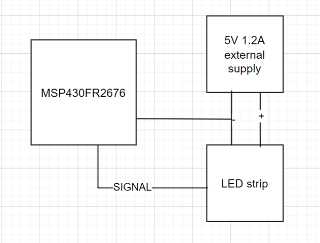
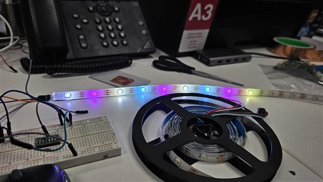
我将尝试使用 MSP430FR2676复制 Adafruit neopixel LED 的功能。 我发现一个在线库(msp430-NeoPixel-WS2812-Library/README.md、位于主控 mjmeli/msp430-NeoPixel-WS2812-Library··GitHub)、该库已在本论坛中讨论、并尝试根据 MSP430FR2676的数据表对其进行编辑。 但我无法打开 LED。 在这方面、您能帮忙吗?我在下面附上了代码。  

非常感谢
Criton

#include <msp430.h>

#define OUTPUT_PIN	(0x04)  //px.2 on msp430fr2676
#define NUM_LEDS    (12)    // NUMBER OF LEDS IN YOUR STRIP

// Useful typedefs
typedef unsigned char u_char;	// 8 bit
typedef unsigned int u_int;     // 16 bit
// Transmit codes
#define HIGH_CODE	(0xF0)      // b11110000 
#define LOW_CODE    (0xC0)      // b11000000
// Configure processor to output to data strip
void initStrip(void);
// Send colors to the strip and show them. Disables interrupts while processing.
void showStrip(void);
// Set the color of a certain LED
void setLEDColor(u_int p, u_char r, u_char g, u_char b);
// Clear the color of all LEDs (make them black/off)
void clearStrip(void);
// Fill the strip with a solid color. This will update the strip.
void fillStrip(u_char r, u_char g, u_char b);

#include <msp430.h>
#include "msp430fr2676.h"
#include "rgb.h"

typedef struct {
    u_char red;
    u_char green;
    u_char blue;
} LED;

LED leds[NUM_LEDS] = { { 0, 0, 0 } };

// Initializes everything needed to use this library. This clears the strip.
void initStrip()
{
    P1SEL0 |= BIT4 | BIT5 | BIT6;

    FRCTL0 = FRCTLPW | NWAITS_1;

    __bis_SR_register(SCG0);    // disable FLL
    CSCTL3 |= SELREF__REFOCLK;  // Set REFO as FLL reference source
    CSCTL0 = 0;                 // clear DCO and MOD registers
    CSCTL1 &= ~(DCORSEL_7);     // Clear DCO frequency select bits first
    CSCTL1 |= DCORSEL_5;        // Set DCO = 16MHz
    CSCTL2 = FLLD_0 + 487;      // set to fDCOCLKDIV = (FLLN + 1)*(fFLLREFCLK/n)
                                //                   = (487 + 1)*(32.768 kHz/1)
                                //                   = 16 MHz

    __delay_cycles(3);
    __bic_SR_register(SCG0);                        // enable FLL
    while(CSCTL7 & (FLLUNLOCK0 | FLLUNLOCK1));      // FLL locked
    clearStrip();   
}

// Sets the color of a certain LED (0 indexed)
void setLEDColor(u_int p, u_char r, u_char g, u_char b) {
    leds[p].red = r;
    leds[p].green = g;
    leds[p].blue = b;
}

// Send colors to the strip and show them. Disables interrupts while processing.
void showStrip() {
    __bic_SR_register(GIE);           // disable interrupts
    // send RGB color for every LED
    int i, j;
    for (i = 0; i < NUM_LEDS; i++) {

        u_char rgb[3] = { leds[i].green, leds[i].red, leds[i].blue }; // get RGB color for this LED
        // send green, then red, then blue
        for (j = 0; j < 3; j++) {
        u_char mask = 0x04;    // b0000100

            while (mask != 0) { 
                 while (! UCB0IFG)
                 ;
                 if (rgb[j] & mask) {        // most significant bit first
                    UCB0TXBUF = HIGH_CODE;  // send 1
                } else {
                    UCB0TXBUF = LOW_CODE;   // send 0
                }
                 mask >>= 1;  // check next bit
            }
        }
    }
    // send RES code for at least 50 us (800 cycles at 16 MHz)
    __delay_cycles(800);
    __bis_SR_register(GIE);    // enable interrupts
}

// Clear the color of all LEDs (make them black/off)
void clearStrip() {
    fillStrip(0x00, 0x00, 0x00);  // black
}

// Fill the strip with a solid color. This will update the strip.
void fillStrip(u_char r, u_char g, u_char b) {
    int i;
    for (i = 0; i < NUM_LEDS; i++) {
        setLEDColor(i, r, g, b);  // set all LEDs to specified color
    }
    showStrip();  // refresh strip
}

void gradualFill(u_int n, u_char r, u_char g, u_char b);

int main(void) {

      WDTCTL = WDTPW | WDTHOLD; 

      initStrip();
      fillStrip(0xFF, 0x00, 0x00);
      showStrip();
     
     while (1) {
        gradualFill(NUM_LEDS, 0x00, 0xFF, 0x00);  // green
        gradualFill(NUM_LEDS, 0x00, 0x00, 0xFF);  // blue
        gradualFill(NUM_LEDS, 0xFF, 0x00, 0xFF);  // magenta
        gradualFill(NUM_LEDS, 0xFF, 0xFF, 0x00);  // yellow
        gradualFill(NUM_LEDS, 0x00, 0xFF, 0xFF);  // cyan
        gradualFill(NUM_LEDS, 0xFF, 0x00, 0x00);  // red
    }
}
void gradualFill(u_int n, u_char r, u_char g, u_char b){
    int i;
    for (i = 0; i < n; i++){        // n is number of LEDs
        setLEDColor(i, r, g, b);
        showStrip();
                _delay_cycles(1000000);       // lazy delay
    }
}

  • 请注意,本文内容源自机器翻译,可能存在语法或其它翻译错误,仅供参考。如需获取准确内容,请参阅链接中的英语原文或自行翻译。

    通过检查、我看到有几个小部件丢失:

    1) 1)没有要配置 UCB0的内容。 从原文翻译、可能看起来像:

        P1SEL0 |= OUTPUT_PIN;    // configure output pin as SPI output
        P1SEL1 &= ~OUTPUT_PIN;   // P1.2 as UCB0SIMO per SLASEO5D Table 9-23
        UCB0CTLW0 |= UCCKPH + UCMSB + UCMST + UCSYNC + UCSSEL_2; // 3-pin, MSB, 8-bit SPI master
        UCB0BR0 = 3;            // 16 MHz / 3 = .1875 us per bit
        UCB0BR1 = 0;
        UCB0CTLW0 &= ~UCSWRST;   // Initialize USCI state machine
    

    我为您选择了 P1.2。 P4.6也提供了 UCB0SIMO

    2)在线路中

    > while (! UCB0IFG)

    IFG 寄存器可以 设置其他位。 请尝试改用:

                    while (!(UCB0IFG & UCTXIFG))
    

    我还没有试过这个(我没有这些设备)、但我认为是对的。

  • 请注意,本文内容源自机器翻译,可能存在语法或其它翻译错误,仅供参考。如需获取准确内容,请参阅链接中的英语原文或自行翻译。

    Bruce、您好!

    非常感谢您的联系。 我做出了这些改变、这些改变仍然亮起。 我已尝试将信号引脚连接到 p1.2和 p4.6。 我附上了供您参考的代码。

    非常感谢、此致、
    Criton


    #include <msp430.h>
    #include "msp430fr2676.h"
    #include "rgb.h"
    
    typedef struct {
        u_char red;
        u_char green;
        u_char blue;
    } LED;
    
    LED leds[NUM_LEDS] = { { 0, 0, 0 } };
    
    // Initializes everything needed to use this library. This clears the strip.
    void initStrip()
    {
        P1SEL0 |= OUTPUT_PIN;    // configure output pin as SPI output
        P1SEL1 &= ~OUTPUT_PIN;   // P1.2 as UCB0SIMO per SLASEO5D Table 9-23
        UCB0CTLW0 |= UCCKPH + UCMSB + UCMST + UCSYNC + UCSSEL_2; // 3-pin, MSB, 8-bit SPI master
        UCB0BR0 = 3;            // 16 MHz / 3 = .1875 us per bit
        UCB0BR1 = 0;
        UCB0CTLW0 &= ~UCSWRST;   // Initialize USCI state machine
        clearStrip();   
    }
    
    // Sets the color of a certain LED (0 indexed)
    void setLEDColor(u_int p, u_char r, u_char g, u_char b) {
        leds[p].red = r;
        leds[p].green = g;
        leds[p].blue = b;
    }
    
    // Send colors to the strip and show them. Disables interrupts while processing.
    void showStrip() {
        __bic_SR_register(GIE);           // disable interrupts
        // send RGB color for every LED
        int i, j;
        for (i = 0; i < NUM_LEDS; i++) {
    
            u_char rgb[3] = { leds[i].green, leds[i].red, leds[i].blue }; // get RGB color for this LED
            // send green, then red, then blue
            for (j = 0; j < 3; j++) {
            u_char mask = 0x04;    // b0000100
    
                while (mask != 0) { 
                     while (!(UCB0IFG & UCTXIFG))
                     ;
                     if (rgb[j] & mask) {        // most significant bit first
                        UCB0TXBUF = HIGH_CODE;  // send 1
                    } else {
                        UCB0TXBUF = LOW_CODE;   // send 0
                    }
                     mask >>= 1;  // check next bit
                }
            }
        }
        // send RES code for at least 50 us (800 cycles at 16 MHz)
        __delay_cycles(800);
        __bis_SR_register(GIE);    // enable interrupts
    }
    
    // Clear the color of all LEDs (make them black/off)
    void clearStrip() {
        fillStrip(0x00, 0x00, 0x00);  // black
    }
    
    // Fill the strip with a solid color. This will update the strip.
    void fillStrip(u_char r, u_char g, u_char b) {
        int i;
        for (i = 0; i < NUM_LEDS; i++) {
            setLEDColor(i, r, g, b);  // set all LEDs to specified color
        }
        showStrip();  // refresh strip
    }
    
    void gradualFill(u_int n, u_char r, u_char g, u_char b);
    
    int main(void) {
    
          WDTCTL = WDTPW | WDTHOLD; 
    
          initStrip();
          fillStrip(0xFF, 0xFF, 0xFF);
          showStrip();
        
         while (1) {
            gradualFill(NUM_LEDS, 0x00, 0xFF, 0x00);  // green
            gradualFill(NUM_LEDS, 0x00, 0x00, 0xFF);  // blue
            gradualFill(NUM_LEDS, 0xFF, 0x00, 0xFF);  // magenta
            gradualFill(NUM_LEDS, 0xFF, 0xFF, 0x00);  // yellow
            gradualFill(NUM_LEDS, 0x00, 0xFF, 0xFF);  // cyan
            gradualFill(NUM_LEDS, 0xFF, 0x00, 0x00);  // red
        }
    }
    void gradualFill(u_int n, u_char r, u_char g, u_char b){
        int i;
        for (i = 0; i < n; i++){        // n is number of LEDs
            setLEDColor(i, r, g, b);
            showStrip();
                    _delay_cycles(1000000);       // lazy delay
        }
    }

  • 请注意,本文内容源自机器翻译,可能存在语法或其它翻译错误,仅供参考。如需获取准确内容,请参阅链接中的英语原文或自行翻译。

    好像你丢失了将 CPU 时钟(实际上是 SMCLK)设置为16MHz 的代码。 ("FRCTL="向下到"while (CSCTL7"。)

    该代码可能属于 main()。

  • 请注意,本文内容源自机器翻译,可能存在语法或其它翻译错误,仅供参考。如需获取准确内容,请参阅链接中的英语原文或自行翻译。

    您好:)、

    我不明白你刚才说的是什么。 你说的是从我发送的用于为16MHz 设定时钟的初始代码中删除的这段代码吗? 我应该保持它并尝试吗?.  

  • 请注意,本文内容源自机器翻译,可能存在语法或其它翻译错误,仅供参考。如需获取准确内容,请参阅链接中的英语原文或自行翻译。

    是的,你应该把这个序列放回,虽然可能在 main ()中,而不是在 initStrip ()中。

    复位后、MCU 时钟(MCLK/SMCLK)在1MHz 下运行、这是因为作者指出速度太慢而无法获得正确的位时序。 我想象在较低速度时一切看起来都像一个 RES 脉冲。

  • 请注意,本文内容源自机器翻译,可能存在语法或其它翻译错误,仅供参考。如需获取准确内容,请参阅链接中的英语原文或自行翻译。

    感谢您及时回复我。 但是、如果我在函数中执行它、效果会与在主函数中传递的效果相同吗? 我在 main 中调用它、但它仍然没有亮起相同的东西。

    我附上了供您参考的代码。

    很好的享受
    Criton

    #include <msp430.h>
    #include "msp430fr2676.h"
    #include "rgb.h"
    
    typedef struct {
        u_char red;
        u_char green;
        u_char blue;
    } LED;
    
    LED leds[NUM_LEDS] = { { 0, 0, 0 } };
    
    // Initializes everything needed to use this library. This clears the strip.
    void initStrip()
    {
        P1SEL0 |= OUTPUT_PIN;    // configure output pin as SPI output
        P1SEL1 &= ~OUTPUT_PIN;   // P1.2 as UCB0SIMO per SLASEO5D Table 9-23
        UCB0CTLW0 |= UCCKPH + UCMSB + UCMST + UCSYNC + UCSSEL_2; // 3-pin, MSB, 8-bit SPI master
        UCB0BR0 = 3;            // 16 MHz / 3 = .1875 us per bit
        UCB0BR1 = 0;
        UCB0CTLW0 &= ~UCSWRST;   // Initialize USCI state machine
        clearStrip();   
    }
    
    // Sets the color of a certain LED (0 indexed)
    void setLEDColor(u_int p, u_char r, u_char g, u_char b) {
        leds[p].red = r;
        leds[p].green = g;
        leds[p].blue = b;
    }
    
    // Send colors to the strip and show them. Disables interrupts while processing.
    void showStrip() {
        __bic_SR_register(GIE);           // disable interrupts
        // send RGB color for every LED
        int i, j;
        for (i = 0; i < NUM_LEDS; i++) {
    
            u_char rgb[3] = { leds[i].green, leds[i].red, leds[i].blue }; // get RGB color for this LED
            // send green, then red, then blue
            for (j = 0; j < 3; j++) {
            u_char mask = 0x04;    // b0000100
    
                while (mask != 0) { 
                     while (!(UCB0IFG & UCTXIFG))
                     ;
                     if (rgb[j] & mask) {        // most significant bit first
                        UCB0TXBUF = HIGH_CODE;  // send 1
                    } else {
                        UCB0TXBUF = LOW_CODE;   // send 0
                    }
                     mask >>= 1;  // check next bit
                }
            }
        }
        // send RES code for at least 50 us (800 cycles at 16 MHz)
        __delay_cycles(800);
        __bis_SR_register(GIE);    // enable interrupts
    }
    
    // Clear the color of all LEDs (make them black/off)
    void clearStrip() {
        fillStrip(0x00, 0x00, 0x00);  // black
    }
    
    // Fill the strip with a solid color. This will update the strip.
    void fillStrip(u_char r, u_char g, u_char b) {
        int i;
        for (i = 0; i < NUM_LEDS; i++) {
            setLEDColor(i, r, g, b);  // set all LEDs to specified color
        }
        showStrip();  // refresh strip
    }
    
    void gradualFill(u_int n, u_char r, u_char g, u_char b);
    
    int main(void) {
    
          WDTCTL = WDTPW | WDTHOLD; 
    
            initStrip();
            __bis_SR_register(SCG0);    // disable FLL
            CSCTL3 |= SELREF__REFOCLK;  // Set REFO as FLL reference source
            CSCTL0 = 0;                 // clear DCO and MOD registers
            CSCTL1 &= ~(DCORSEL_7);     // Clear DCO frequency select bits first
            CSCTL1 |= DCORSEL_5;        // Set DCO = 16MHz
            CSCTL2 = FLLD_0 + 487;      // set to fDCOCLKDIV = (FLLN + 1)*(fFLLREFCLK/n)
                                    //                   = (487 + 1)*(32.768 kHz/1)
                                    //                   = 16 MHz
    
            __delay_cycles(3);
            __bic_SR_register(SCG0);                        // enable FLL
            while(CSCTL7 & (FLLUNLOCK0 | FLLUNLOCK1));      // FLL locked
            fillStrip(0xFF, 0xFF, 0xFF);
            showStrip();
        
         while (1) {
            gradualFill(NUM_LEDS, 0x00, 0xFF, 0x00);  // green
            gradualFill(NUM_LEDS, 0x00, 0x00, 0xFF);  // blue
            gradualFill(NUM_LEDS, 0xFF, 0x00, 0xFF);  // magenta
            gradualFill(NUM_LEDS, 0xFF, 0xFF, 0x00);  // yellow
            gradualFill(NUM_LEDS, 0x00, 0xFF, 0xFF);  // cyan
            gradualFill(NUM_LEDS, 0xFF, 0x00, 0x00);  // red
        }
    }
    void gradualFill(u_int n, u_char r, u_char g, u_char b){
        int i;
        for (i = 0; i < n; i++){        // n is number of LEDs
            setLEDColor(i, r, g, b);
            showStrip();
                    _delay_cycles(1000000);       // lazy delay
        }
    }

  • 请注意,本文内容源自机器翻译,可能存在语法或其它翻译错误,仅供参考。如需获取准确内容,请参阅链接中的英语原文或自行翻译。

    您可能应该在调用 initStrip 之前而不是在调用之后设置时钟。 不过、这只会影响初始的 clearStrip 调用。

    我注意到的其他内容缺失(作者不必在 F2/G2器件上执行此操作、但 FRx 器件需要):

    > PM5CTL0并且=~μ A LOCKLPM5;  //启用 GPIO

    可以在 initStrip 调用之前随时执行此操作。

    您是否能够完全确定您的条带的供电是否正常? 我(模糊)记得,一条12倍的条消耗了相当数量的权力。

  • 请注意,本文内容源自机器翻译,可能存在语法或其它翻译错误,仅供参考。如需获取准确内容,请参阅链接中的英语原文或自行翻译。

    Bruce、您好!

    非常感谢您的回应我已附上我的代码和电路连接供您参考。 实际上、我正在使用外部电源来为 LED 供电。 然而,即使修改代码后, LED 指示灯不会照亮他们应该的方式。 我还尝试将接头中使用的 LED 数量更改为几个数字。

    此致、
    Criton

    #include <msp430.h>
    #include "msp430fr2676.h"
    #include "rgb.h"
    
    typedef struct {
        u_char red;
        u_char green;
        u_char blue;
    } LED;
    
    LED leds[NUM_LEDS] = { { 0, 0, 0 } };
    
    // Initializes everything needed to use this library. This clears the strip.
    void initStrip()
    {
        P1SEL0 |= OUTPUT_PIN;    // configure output pin as SPI output
        P1SEL1 &= ~OUTPUT_PIN;   // P1.2 as UCB0SIMO per SLASEO5D Table 9-23
        UCB0CTLW0 |= UCCKPH + UCMSB + UCMST + UCSYNC + UCSSEL_2; // 3-pin, MSB, 8-bit SPI master
        UCB0BR0 = 3;            // 16 MHz / 3 = .1875 us per bit
        UCB0BR1 = 0;
        UCB0CTLW0 &= ~UCSWRST;   // Initialize USCI state machine
        clearStrip();   
    }
    
    // Sets the color of a certain LED (0 indexed)
    void setLEDColor(u_int p, u_char r, u_char g, u_char b) {
        leds[p].red = r;
        leds[p].green = g;
        leds[p].blue = b;
    }
    
    // Send colors to the strip and show them. Disables interrupts while processing.
    void showStrip() {
        __bic_SR_register(GIE);           // disable interrupts
        // send RGB color for every LED
        int i, j;
        for (i = 0; i < NUM_LEDS; i++) {
    
            u_char rgb[3] = { leds[i].green, leds[i].red, leds[i].blue }; // get RGB color for this LED
            // send green, then red, then blue
            for (j = 0; j < 3; j++) {
            u_char mask = 0x04;    // b0000100
    
                while (mask != 0) { 
                     while (!(UCB0IFG & UCTXIFG))
                     ;
                     if (rgb[j] & mask) {        // most significant bit first
                        UCB0TXBUF = HIGH_CODE;  // send 1
                    } else {
                        UCB0TXBUF = LOW_CODE;   // send 0
                    }
                     mask >>= 1;  // check next bit
                }
            }
        }
        // send RES code for at least 50 us (800 cycles at 16 MHz)
        __delay_cycles(800);
        __bis_SR_register(GIE);    // enable interrupts
    }
    
    // Clear the color of all LEDs (make them black/off)
    void clearStrip() {
        fillStrip(0x00, 0x00, 0x00);  // black
    }
    
    // Fill the strip with a solid color. This will update the strip.
    void fillStrip(u_char r, u_char g, u_char b) {
        int i;
        for (i = 0; i < NUM_LEDS; i++) {
            setLEDColor(i, r, g, b);  // set all LEDs to specified color
        }
        showStrip();  // refresh strip
    }
    
    void gradualFill(u_int n, u_char r, u_char g, u_char b);
    
    int main(void) {
    
          WDTCTL = WDTPW | WDTHOLD;  
    
            CSCTL3 |= SELREF__REFOCLK;  // Set REFO as FLL reference source
            CSCTL0 = 0;                 // clear DCO and MOD registers
            CSCTL1 &= ~(DCORSEL_7);     // Clear DCO frequency select bits first
            CSCTL1 |= DCORSEL_5;        // Set DCO = 16MHz
            CSCTL2 = FLLD_0 + 487;      // set to fDCOCLKDIV = (FLLN + 1)*(fFLLREFCLK/n)
                                    //                   = (487 + 1)*(32.768 kHz/1)
                                    //                   = 16 MHz
    
            __delay_cycles(3);
            __bic_SR_register(SCG0);                        // enable FLL  
            PM5CTL0 &= ~LOCKLPM5; 
            initStrip();
            fillStrip(0xFF, 0xFF, 0xFF);
            showStrip();
            clearStrip();
        
         while (1) {
            gradualFill(NUM_LEDS, 0x00, 0xFF, 0x00);  // green
            gradualFill(NUM_LEDS, 0x00, 0x00, 0xFF);  // blue
            gradualFill(NUM_LEDS, 0xFF, 0x00, 0xFF);  // magenta
            gradualFill(NUM_LEDS, 0xFF, 0xFF, 0x00);  // yellow
            gradualFill(NUM_LEDS, 0x00, 0xFF, 0xFF);  // cyan
            gradualFill(NUM_LEDS, 0xFF, 0x00, 0x00);  // red
        }
    }
    void gradualFill(u_int n, u_char r, u_char g, u_char b){
        int i;
        for (i = 0; i < n; i++){        // n is number of LEDs
            setLEDColor(i, r, g, b);
            showStrip();
                    _delay_cycles(1000000);       // lazy delay
        }
    }


  • 请注意,本文内容源自机器翻译,可能存在语法或其它翻译错误,仅供参考。如需获取准确内容,请参阅链接中的英语原文或自行翻译。

    我也忘了提到 LED 不改变颜色,他们只是保持明亮的白色。 当我将 LED 数量设置为50时、15个 LED 会亮起白色并保持原样、它们确实会按照 while (1)循环中定义的方式改变颜色。

  • 请注意,本文内容源自机器翻译,可能存在语法或其它翻译错误,仅供参考。如需获取准确内容,请参阅链接中的英语原文或自行翻译。

    > u_char mask = 0x04;// b0000100

    这仅发送3位/颜色、但原始代码以0x80的掩码开始、因此它发送8位/颜色。 (数字8也与我的 WS2812B 数据表副本相匹配。)

    您更改此内容的原因是什么?

  • 请注意,本文内容源自机器翻译,可能存在语法或其它翻译错误,仅供参考。如需获取准确内容,请参阅链接中的英语原文或自行翻译。

    哎呀、这是个拼写错误。

    但这并不能解决问题。

  • 请注意,本文内容源自机器翻译,可能存在语法或其它翻译错误,仅供参考。如需获取准确内容,请参阅链接中的英语原文或自行翻译。

    它更像是即使我按下 MSP 上的 RESET、LED 也会亮起并一直亮起。 更像,如果我保持数量的 LED =10, 9发光,其中8是白色的,第9是绿色的。 当我将其设置为20时、16个 LED 变为白光、4个 LED 保持熄灭状态。

    非常感谢  

  • 请注意,本文内容源自机器翻译,可能存在语法或其它翻译错误,仅供参考。如需获取准确内容,请参阅链接中的英语原文或自行翻译。

    我正在了解这个内核循环(写入 SPI)、并且很想知道它是否能够跟上步伐。 每个周期必须在(br0=3)*(8位)=24个 CPU 周期内完成、否则将落后。 这对于少量 LED 而言可能不可见、但它持续的时间越长、信号(Vs 时钟)将漂移得越远。

    可以尝试以下操作(速度很快):

    1)设置速度的优化级别:在"Build Settings->Build->Compiler->Optimization"中、将"level"设置为"4"、将"coefforts"设置为"5 (speed)"。  

    2) 2)此行:

    > u_char RGB[3]={LEDS[i].green、LEDS[i].red、LEDS[i].blue};//获取此 LED 的 RGB 颜色

    将数据从全局复制到堆栈没有任何益处。 (这一行是内核循环的一部分。) 最初使用的:

    > u_char * rgb =(u_char *)&LEDS[i];//获取此 LED 的 GRB 颜色

    这几乎是合法的、不涉及数据复制。

  • 请注意,本文内容源自机器翻译,可能存在语法或其它翻译错误,仅供参考。如需获取准确内容,请参阅链接中的英语原文或自行翻译。

    此外、您似乎丢失了此行:

    > FRCTL0 = FRCTLPW | NWAITS_1;

    它应该出现在 main()中的时钟配置之前。

    (当我忘记它时、编译器通常会向我发出警告。)

  • 请注意,本文内容源自机器翻译,可能存在语法或其它翻译错误,仅供参考。如需获取准确内容,请参阅链接中的英语原文或自行翻译。

    您好、非常感谢您的答复。

    我尝试了使用您提到的更改调整代码。 唯一有效的更改是更改编译配置中的优化级别和速度。  

    我不明白改变这意味着什么? 请您解释一下。

    1) u_char RGB[3]={LEDS[i].green、LEDS[i].red、LEDS[i].blue}; 更改为  u_char * RGB =(u_char *)&LEDS[i];
    2)  FRCTL0 = FRCTLPW | NWAITS_1;

    以下问题仍然存在阻抗。

    1)程序中提到的 LED 数量与编号不匹配 唤醒的 LED。
    2) LED 的颜色不工作如代码中所述(我已附上图像供您参考)。  例如、下面的代码只有一个函数、该函数应在10个 LED 上输出绿色、但在任何 LED 上都不显示绿色、而是其他一些颜色、只有9个 LED 亮起。


    您能否告诉我、更改速度和优化如何帮助 LED 产生运转效果?


    非常感谢、此致、
    Criton

    #include <msp430.h>
    #include "msp430fr2676.h"
    #include "rgb.h"
    
    typedef struct {
        u_char red;
        u_char green;
        u_char blue;
    } LED;
    
    LED leds[NUM_LEDS] = { { 0, 0, 0 } };
    
    // Initializes everything needed to use this library. This clears the strip.
    void initStrip()
    {
        P1SEL0 |= OUTPUT_PIN;    // configure output pin as SPI output
        P1SEL1 &= ~OUTPUT_PIN;   // P1.2 as UCB0SIMO per SLASEO5D Table 9-23
        UCB0CTLW0 |= UCCKPH + UCMSB + UCMST + UCSYNC + UCSSEL_2; // 3-pin, MSB, 8-bit SPI master
        UCB0BR0 = 3;            // 16 MHz / 3 = .1875 us per bit
        UCB0BR1 = 0;
        UCB0CTLW0 &= ~UCSWRST;   // Initialize USCI state machine
        clearStrip();   
    }
    
    // Sets the color of a certain LED (0 indexed)
    void setLEDColor(u_int p, u_char r, u_char g, u_char b) {
        leds[p].red = r;
        leds[p].green = g;
        leds[p].blue = b;
    }
    
    // Send colors to the strip and show them. Disables interrupts while processing.
    void showStrip() {
        __bic_SR_register(GIE);           // disable interrupts
        // send RGB color for every LED
        int i, j;
        for (i = 0; i < NUM_LEDS; i++) {
             u_char *rgb = (u_char *)&leds[i];
          //u_char rgb[3] = { leds[i].green, leds[i].red, leds[i].blue };   // get RGB color for this LED
            // send green, then red, then blue
            for (j = 0; j < 3; j++) {
            u_char mask = 0x80;    // b0000100
    
                while (mask != 0) { 
                     while (!(UCB0IFG & UCTXIFG))
                     ;
                     if (rgb[j] & mask) {        // most significant bit first
                        UCB0TXBUF = HIGH_CODE;  // send 1
                    } else {
                        UCB0TXBUF = LOW_CODE;   // send 0
                    }
                     mask >>= 1;  // check next bit
                }
            }
        }
        // send RES code for at least 50 us (800 cycles at 16 MHz)
        __delay_cycles(800);
        __bis_SR_register(GIE);    // enable interrupts
    }
    
    // Clear the color of all LEDs (make them black/off)
    void clearStrip() {
        fillStrip(0x00, 0x00, 0x00);  // black
    }
    
    // Fill the strip with a solid color. This will update the strip.
    void fillStrip(u_char r, u_char g, u_char b) {
        int i;
        for (i = 0; i < NUM_LEDS; i++) {
            setLEDColor(i, r, g, b);  // set all LEDs to specified color
        }
        showStrip();  // refresh strip
    }
    
    void gradualFill(u_int n, u_char r, u_char g, u_char b);
    
    int main(void) {
    
          WDTCTL = WDTPW | WDTHOLD;  
    
            FRCTL0 = FRCTLPW | NWAITS_1;
            CSCTL3 |= SELREF__REFOCLK;  // Set REFO as FLL reference source
            CSCTL0 = 0;                 // clear DCO and MOD registers
            CSCTL1 &= ~(DCORSEL_7);     // Clear DCO frequency select bits first
            CSCTL1 |= DCORSEL_5;        // Set DCO = 16MHz
            CSCTL2 = FLLD_0 + 487;      // set to fDCOCLKDIV = (FLLN + 1)*(fFLLREFCLK/n)
                                    //                   = (487 + 1)*(32.768 kHz/1)
                                    //                   = 16 MHz
    
            __delay_cycles(3);
            __bic_SR_register(SCG0);                        // enable FLL  
            PM5CTL0 &= ~LOCKLPM5; 
            initStrip();
            clearStrip();
            fillStrip(0xFF, 0xFF, 0xFF);
            showStrip();
        
         while (1) {
            gradualFill(NUM_LEDS, 0x00, 0xFF, 0x00);  // green
           // gradualFill(NUM_LEDS, 0x00, 0x00, 0xFF);  // blue
           // gradualFill(NUM_LEDS, 0xFF, 0x00, 0xFF);  // magenta
          //  gradualFill(NUM_LEDS, 0xFF, 0xFF, 0x00);  // yellow
           // gradualFill(NUM_LEDS, 0x00, 0xFF, 0xFF);  // cyan
           // gradualFill(NUM_LEDS, 0xFF, 0x00, 0x00);  // red
        }
    }
    void gradualFill(u_int n, u_char r, u_char g, u_char b){
        int i;
        for (i = 0; i < n; i++){        // n is number of LEDs
            setLEDColor(i, r, g, b);
            showStrip();
                    _delay_cycles(100000);       // lazy delay
        }
    }

  • 请注意,本文内容源自机器翻译,可能存在语法或其它翻译错误,仅供参考。如需获取准确内容,请参阅链接中的英语原文或自行翻译。

    以这种方式驾驶 neopixels 是一个挑战。 它们具有非常具体的时序要求、而且没有太大的裕度。 此处使用的方法是使用 SPI 端口通过数据输出近似值。

    因此、在前一个位完成之前将下一位数据写入 TXBUF 非常重要。 这充其量是个棘手的问题、因此增加到16MHz 的 CPU 时钟会有所帮助。 但是、对于任何大于8MHz 的时钟速度、您必须将 FRAM 配置为等待状态。 否则会 出现访问时间错误和 CPU 复位。

    该库是为 G2553编写的、不存在 FRAM 等待问题、因此同一循环在 G2553上运行速度略快。 (FRAM 缓存在这方面很有用、但使得计算代码执行时间变得困难。)

  • 请注意,本文内容源自机器翻译,可能存在语法或其它翻译错误,仅供参考。如需获取准确内容,请参阅链接中的英语原文或自行翻译。

    您好、David Schultz。  

    非常感谢您的答复和解释。 B ü@BruceMcKenney47378已经提到了我在代码中遗漏的 FRAM 控制语句。 我浏览了参考手册、根据我的理解、它有8个等待状态。 对于我应该使用什么等待状态来实现 Neopixel LED 的正确计时、您是否有任何意见?  也是同样的原因,亮起的 LED 的数量与程序中指定的数字不匹配?  

    我期待您的评论。

    非常感谢
    Criton

  • 请注意,本文内容源自机器翻译,可能存在语法或其它翻译错误,仅供参考。如需获取准确内容,请参阅链接中的英语原文或自行翻译。

    器件数据表中列出了所需的等待状态数。 与一个16MHz 搭配使用。

    此外、请确保发送的位模式正确。 我看到一个对称模式(0xF0)、而我读取的 Neopixel 文档并不接近该模式。 高850ns、低400ns。 高电平部分在150ns 裕度范围内、但低电平不接近。

    您每位有24个 MCLK 周期、这个过程非常严格、需要深入研究 C 编译器正在发射的汇编代码、以查看它是否起作用。

  • 请注意,本文内容源自机器翻译,可能存在语法或其它翻译错误,仅供参考。如需获取准确内容,请参阅链接中的英语原文或自行翻译。

    尊敬的 David:

    @数据表、等待状态与 T Ü V Bruce 所说的状态相同。 但是、高低值的影响我不明白数值与时间的关系。 您能解释一下吗?

    非常感谢、此致、
    Criton

  • 请注意,本文内容源自机器翻译,可能存在语法或其它翻译错误,仅供参考。如需获取准确内容,请参阅链接中的英语原文或自行翻译。

    SPI 用于生成波形、一个段序列、其中每个段(8个 SPI 位)组成一个 Neopixel 位。 在数据表中、每个段都应该看起来像"0代码"或"1代码"波形[我的 WS2812B 数据表没有文档/版本标识;我从 Adafruit]那里获得]。 如果您在 HIGH_CODE 位模式下陷入静噪、您可以看到波形为 T1H、后跟 T1L。 David 为我们检查了算法、结果似乎 high_code=0xf8可能效果更好、但这现在不是您的主要问题。

    SPI 保证每个 SPI 位的时序(0.1875微秒)。 但一旦它耗尽(8个 SPI)位、它就会暂停、从而导致(内部) Neopixel 和 波形时钟彼此分离。 为了防止位数用完、用户需要先将下一个 SPI 字节(Neopixel 位)写入 TXBUF、然后再写入此字节。 对于每个(SPI)字节、SPI 需要3*8=24个 CPU 时钟。 因此、您的循环必须在24个 CPU 时钟内执行才能保持运行。 我通常估算大约5个 CPU 时钟/指令、因此24个时钟可能是5个指令 、我怀疑 循环中的所有这些决策都可以用5个指令完成。 (您未更新所有 LED 的事实也表明您的环路不能正常运行。)

    作者建议,这个代码工作,我不能说他错了,但他没有给出任何测试条件。 我怀疑使用很少数量的 LED 能够更好地工作(时钟漂移累积的时间更短)。   例如1-3、您是否能通过使用更少的 LED 获得合理的结果?

    ---

    主动:如果您准备尝试一些更加雄心勃勃的东西、在开始波形之前、您可以考虑(从 DMA 人员那里获得提示)将整个波形(SPI 字节)作为数组进行预计算。

    阵列将占用(24 * NUM_LED)个字节、但我认为您不会缺少此 MCU 中的 SRAM。 保持判定逻辑、但不是写入 TXBUF、而是写入(例如) SPI_BYTED[]。 然后以类似的方式在突发中执行整个数组

    > for (i = 0 ; i < 24*NUM_LED ;+i) {

    >  while ((UCB0IFG & UCTXIFG)=0)/* empty*/;//将 TXBUF 设为空

    >  UCB0TXBUF = SPI_BYTES[i];  //写入下一个 SPI 字节/Neopixel 位

    >}

    (该循环可能可以进一步简化、但我怀疑优化器会很好地处理它。)

  • 请注意,本文内容源自机器翻译,可能存在语法或其它翻译错误,仅供参考。如需获取准确内容,请参阅链接中的英语原文或自行翻译。

    Bruce、您好!

    非常感谢详细的解释。

    如果您对 high_code 位模式进行深陷、您可以看到波形为 T1H、后跟 T1L。 David 为我们检查了算术、似乎 high_code=0xf8可能更好、[/报价]

     David 提到 High 代码在150ns 容差范围内、但 Low 代码不在。 在你之前的注释中、你提到了高代码0xf8的运行方式会更好、所以在高代码和低代码上会有点混淆。 必须测试它。  

     如果使用较少的 LED、您能获得合理的结果吗?例如1-3?

    并不是真的、当我为3个 LED 放代码时、它不会给我提供预期的颜色另外一件奇怪的事情、我注意到、当我开始调试代码时、第一个 LED 不会亮起、而 LED 2、3和4亮起(当然会使用与代码中提到的颜色不同的颜色)。 现在、当我退出调试会话后按 MSP 上的复位按钮时、第一个 LED 会亮起并保持白色。   

    未经请求:如果您准备尝试一些更加雄心勃勃的东西、在开始波形之前、您可以考虑(获取 DMA 人员的提示)将整个波形(SPI 字节)作为数组进行预计算。

    感谢您的激励和有用提示。 我将使用我们现有的电流驱动器对其进行试用、进一步了解它、然后将其移至 DMA 侧、如果效果不好。 我当前的目的是查看5-10 LED 在给定的命令集下是否可以正常工作。

    非常感谢、此致、
    克里顿:)

    [/quote]
  • 请注意,本文内容源自机器翻译,可能存在语法或其它翻译错误,仅供参考。如需获取准确内容,请参阅链接中的英语原文或自行翻译。

    在你的 MCU 上没有 DMA 控制器、但是如果你这么做、你就可以使用 DMA 控制器。 DMA 操作将取代我发布的循环。

  • 请注意,本文内容源自机器翻译,可能存在语法或其它翻译错误,仅供参考。如需获取准确内容,请参阅链接中的英语原文或自行翻译。

    大家好、Bruce 和 David、

    有一个误解从我的一方,因为 neopixel LED 的是 RGBW 而不是 RGB 导致的问题的颜色。 在上面发布了相同的驱动器(对白色像素进行了一些修改)的情况下、我可以控制 LED 的颜色。 但是、仍然存在的问题是、当我将 LED 数量设置为10、10亮起时、但条带上的第一个 LED 未亮起(在 MCU 上按下 RESET 时、第一个 LED 变为白色、其余的 LED 按定义运行)。 我使用不同数量的 LED 对其进行了测试、亮起的 LED 数量与定义的相同、但条带上的第一个 LED 未亮起。

    我期待听到您的意见/建议。

    非常感谢、此致、
    Criton  

  • 请注意,本文内容源自机器翻译,可能存在语法或其它翻译错误,仅供参考。如需获取准确内容,请参阅链接中的英语原文或自行翻译。

    第一个 LED (a)是否从不亮起或(b)是否始终亮起白色?

    我花了几分钟在 Adafruit 和发现一些 tidbits:

    1) RGBW 有几种型号、包括(至少) GRBW 和 WRGB。

    2)一些 WS2812(B) NeoPixels 能够接受 WS2811协议,该协议以一半的速度运行,不成比例的时序。

    3) Adafruit NeoPixel 库(寻找"canShow")提到一个"锁存"时间(300usec)的延迟,这似乎需要与复位脉冲(50usec)的同时。 我无法判断这是额外时间还是重叠时间。 或者可能是复位脉冲时间、他们只是观察到它需要比记录的时间更长。 在任何情况下、您都可以尝试将 showStrip 中的重置延迟从800=50*16延长到4800=300*16。

  • 请注意,本文内容源自机器翻译,可能存在语法或其它翻译错误,仅供参考。如需获取准确内容,请参阅链接中的英语原文或自行翻译。

    Bruce、您好!

    非常感谢您的建议/意见。 将代码闪存到 MSP430FR2676中后、定义10个 LED 点亮、第一个 LED 不亮起、下一个10个 LED 亮起。 但是、如果我在 MCU 上按下复位、第一个会保持白色(带有 __delay_cycles (800 ); (代码中)、接下来的10个 LED 指示灯将继续工作。 这是我得到的结果。

    此致、
    Criton

  • 请注意,本文内容源自机器翻译,可能存在语法或其它翻译错误,仅供参考。如需获取准确内容,请参阅链接中的英语原文或自行翻译。

    由于每个像素在脉冲传递之前会清除脉冲的时序、因此第一个像素运行不正常表明存在时序问题。