This thread has been locked.

If you have a related question, please click the "Ask a related question" button in the top right corner. The newly created question will be automatically linked to this question.

[参考译文] MSP430FR4131:怪异的 FRAM 使用情况

Guru**** 2376610 points
Other Parts Discussed in Thread: MSP430FR4131
请注意,本文内容源自机器翻译,可能存在语法或其它翻译错误,仅供参考。如需获取准确内容,请参阅链接中的英语原文或自行翻译。

https://e2e.ti.com/support/microcontrollers/msp-low-power-microcontrollers-group/msp430/f/msp-low-power-microcontroller-forum/1443644/msp430fr4131-weird-fram-usage

器件型号:MSP430FR4131

工具与软件:

你好。

我正在使用 CCS V12.6.0.00008 和 msp430fr4131。 我 在此代码中有一个怪异的 FRAM 用法:

//  Built with Code Composer Studio v12
//******************************************************************************
#include <msp430fr4131.h>

#define us      16          // define the the value of uSec to be used in delay & _delay_cycles functions
#define ms      16000       // define the the value of mSec to be used in delay & _delay_cycles functions
#define _5ms    80000       // define the the value of 5mSec to be used in delay & _delay_cycles functions
#define _10ms   160000      // define the the value of 10mSec to be used in delay & _delay_cycles functions
#define _50ms   800000      // define the the value of 50mSec to be used in delay & _delay_cycles functions
#define _100ms  1600000     // define the the value of 100mSec to be used in delay & _delay_cycles functions
#define _sec    16000000    // define the the value of Sec to be used in delay & _delay_cycles functions

//******************************************************************************
void initGPIO()
    {
    // make all inputs
    P1DIR = 0x00; P2DIR = 0x00; P3DIR = 0x00; P4DIR = 0x00;
    P5DIR = 0x00; P6DIR = 0x00; P7DIR = 0x00; P8DIR = 0x00;
    // Enable Pull up/down R
    P1REN = 0xFF; P2REN = 0xFF; P3REN = 0xFF; P4REN = 0xFF;
    P5REN = 0xFF; P6REN = 0xFF; P7REN = 0xFF; P8REN = 0xFF;
    // Make all inputs pulled up
    P1OUT = 0xFF; P2OUT = 0xFF; P3OUT = 0xFF; P4OUT = 0xFF;
    P5OUT = 0xFF; P6OUT = 0xFF; P7OUT = 0xFF; P8OUT = 0xFF;

    // Disable the GPIO power-on default high-impedance mode
    // to activate previously configured port settings
    PM5CTL0 &= ~LOCKLPM5;
    }
//******************************************************************************
void initClock()
    {

    // Configure one FRAM wait state as required by the device data sheet for MCLK
    // operation beyond 8MHz _before_ configuring the clock system.
    FRCTL0 = FRCTLPW | NWAITS_1;

    __bis_SR_register(SCG0);    // disable FLL
    CSCTL3 |= SELREF__REFOCLK;  // Set REFO as FLL reference source
    CSCTL0 = 0;                 // clear DCO and MOD registers
    CSCTL1 &= ~(DCORSEL_7);     // Clear DCO frequency select bits first
    CSCTL1 |= DCORSEL_5;        // Set DCO = 16MHz
    CSCTL2 = FLLD_0 + 487;      // set to fDCOCLKDIV = (FLLN + 1)*(fFLLREFCLK/n)
                                //                   = (487 + 1)*(32.768 kHz/1)
                                //                   = ~16 MHz (= 15990784 Hz)
    __delay_cycles(3);
    __bic_SR_register(SCG0);                        // enable FLL
    while(CSCTL7 & (FLLUNLOCK0 | FLLUNLOCK1));      // FLL locked

    CSCTL4 = SELMS__DCOCLKDIV | SELA__REFOCLK;

    }


//********************************************************
// main program variables
//********************************************************


char batt_body1 = 0;      //  will represent the outer body
char batt_body2 = 0;      //  will represent the outer body
char batt_body3 = 0;      //  will represent the outer body
char batt_body4 = 0;      //  will represent the outer body

char batt_top1 = 0;      //  will represent the top part
char batt_top2 = 0;      //  will represent the top part
char batt_top3 = 0;      //  will represent the top part
char batt_top4 = 0;      //  will represent the top part


void main( void )
{
    WDTCTL = WDTPW | WDTHOLD;   // Stop watch dog timer
    initGPIO();                 // setup digital IO pins
    initClock();                // setup Clock = 16MHz

    _delay_cycles(_sec);        // delay 1


    batt_body1 = 1;
    batt_body2 = 1;
    batt_body3 = 1;
    batt_body4 = 1;

    batt_top1 = 1;
    batt_top2 = 1;
    batt_top3 = 1;
    batt_top4 = 1;


    while (1)
        {
        _delay_cycles(_sec);    // delay 2
        }//END OF while (1)
}// END OF MAIN

按原样代码可得出 FRAM 使用量为798、共3968 20%。

如果移除"delay 1"线路、则  FRAM 将达到 3968 19%中776的 FRAM 用量。

但是、如果移除"delay 2"线路(保持"delay 1")、 则  在3968 6%的情况下、FRAM 使用量将为242。

还有一个问题、如果我保留两个延迟并删除所有八个 batt_XXX 变量分配、    3968 6%的 FRAM 使用量将为264。

那么、具体情况是什么。

谢谢

  • 请注意,本文内容源自机器翻译,可能存在语法或其它翻译错误,仅供参考。如需获取准确内容,请参阅链接中的英语原文或自行翻译。

    尊敬的 Sami:

    我不确定删除 delay2和保持 delay1为什么会在代码大小方面产生差异。  不应该这样做、因为 时钟初始化过程中还有另一个"__delay_cycles (3)"。  编译器已经链接到该函数中。  向 func _delay_cycles ()添加额外的调用应该只添加几个字节用于处理栈进入和退出。

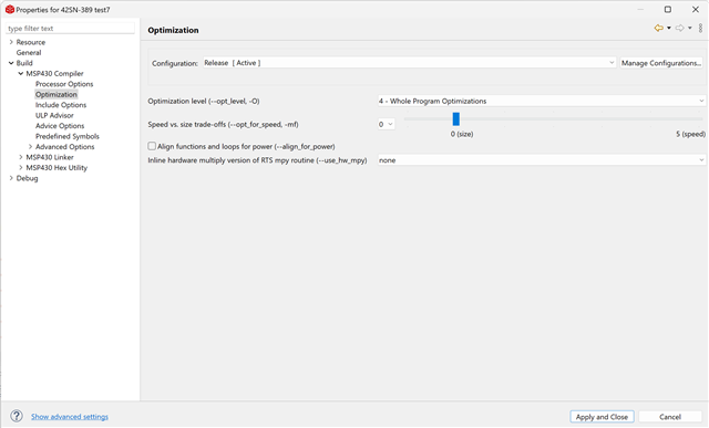
    您使用哪些编译器优化设置?

    对于这些变量、如果从空工程开始、然后只添加一个变量、并在 main 之外声明和定义该变量、链接器将在 main 开始之前包含这些变量的运行时初始化代码、但这会使代码大小变大(在本例中看起来大约为~500个字节)。   

    #include <msp430.h> 
    
    #define RUNTIME_INIT
    
    #ifdef RUNTIME_INIT
        /* Declare only */
        char peach = 0;
    #else
        char peach;
    #endif
    
    /**
     * main.c
     */
    int main(void)
    {
    
    	WDTCTL = WDTPW | WDTHOLD;	// stop watchdog timer
    
    	/* Comment out variable peach and code size is 48 bytes */
    	peach = 1;
    	return 0;
    }

    如果您只在 main 之外声明该变量、但然后在 main 中定义它(向其分配一个值)、如下所示、则大小仅为230字节。  不需要在 main 之前进行运行时初始化、因为在 main 中为变量分配了一个值。  

    #include <msp430.h> 
    
    //#define RUNTIME_INIT
    
    #ifdef RUNTIME_INIT
        /* Declare only */
        char peach = 0;
    #else
        char peach;
    #endif
    
    /**
     * main.c
     */
    int main(void)
    {
    
    	WDTCTL = WDTPW | WDTHOLD;	// stop watchdog timer
    
    	/* Comment out variable peach and code size is 48 bytes */
    	peach = 1;
    	return 0;
    }

    当然、如果您声明或定义了并且根本不使用该变量、编译就足够智能、不能包含或添加关联的运行时初始化代码、从而导致代码大小仅为48字节。

    #include <msp430.h> 
    
    //#define RUNTIME_INIT
    
    #ifdef RUNTIME_INIT
        /* Declare only */
        char peach = 0;
    #else
        char peach;
    #endif
    
    /**
     * main.c
     */
    int main(void)
    {
    
    	WDTCTL = WDTPW | WDTHOLD;	// stop watchdog timer
    
    	/* Comment out variable peach and code size is 48 bytes */
    	//peach = 1;
    	return 0;
    }

  • 请注意,本文内容源自机器翻译,可能存在语法或其它翻译错误,仅供参考。如需获取准确内容,请参阅链接中的英语原文或自行翻译。

    //  Built with Code Composer Studio v12
    //******************************************************************************
    #include <msp430fr4131.h>
    
    #define us      16          // define the the value of uSec to be used in delay & _delay_cycles functions
    #define ms      16000       // define the the value of mSec to be used in delay & _delay_cycles functions
    #define _5ms    80000       // define the the value of 5mSec to be used in delay & _delay_cycles functions
    #define _10ms   160000      // define the the value of 10mSec to be used in delay & _delay_cycles functions
    #define _50ms   800000      // define the the value of 50mSec to be used in delay & _delay_cycles functions
    #define _100ms  1600000     // define the the value of 100mSec to be used in delay & _delay_cycles functions
    #define _sec    16000000    // define the the value of Sec to be used in delay & _delay_cycles functions
    
    //******************************************************************************
    void initGPIO()
        {
        // make all inputs
        P1DIR = 0x00; P2DIR = 0x00; P3DIR = 0x00; P4DIR = 0x00;
        P5DIR = 0x00; P6DIR = 0x00; P7DIR = 0x00; P8DIR = 0x00;
        // Enable Pull up/down R
        P1REN = 0xFF; P2REN = 0xFF; P3REN = 0xFF; P4REN = 0xFF;
        P5REN = 0xFF; P6REN = 0xFF; P7REN = 0xFF; P8REN = 0xFF;
        // Make all inputs pulled up
        P1OUT = 0xFF; P2OUT = 0xFF; P3OUT = 0xFF; P4OUT = 0xFF;
        P5OUT = 0xFF; P6OUT = 0xFF; P7OUT = 0xFF; P8OUT = 0xFF;
    
        // Disable the GPIO power-on default high-impedance mode
        // to activate previously configured port settings
        PM5CTL0 &= ~LOCKLPM5;
        }
    //******************************************************************************
    void initClock()
        {
    
        // Configure one FRAM wait state as required by the device data sheet for MCLK
        // operation beyond 8MHz _before_ configuring the clock system.
        FRCTL0 = FRCTLPW | NWAITS_1;
    
        __bis_SR_register(SCG0);    // disable FLL
        CSCTL3 |= SELREF__REFOCLK;  // Set REFO as FLL reference source
        CSCTL0 = 0;                 // clear DCO and MOD registers
        CSCTL1 &= ~(DCORSEL_7);     // Clear DCO frequency select bits first
        CSCTL1 |= DCORSEL_5;        // Set DCO = 16MHz
        CSCTL2 = FLLD_0 + 487;      // set to fDCOCLKDIV = (FLLN + 1)*(fFLLREFCLK/n)
                                    //                   = (487 + 1)*(32.768 kHz/1)
                                    //                   = ~16 MHz (= 15990784 Hz)
        __delay_cycles(3);
        __bic_SR_register(SCG0);                        // enable FLL
        while(CSCTL7 & (FLLUNLOCK0 | FLLUNLOCK1));      // FLL locked
    
        CSCTL4 = SELMS__DCOCLKDIV | SELA__REFOCLK;
    
        }
    
    
    //********************************************************
    // main program variables
    //********************************************************
    
    
    char batt_body1;      //  will represent the outer body
    char batt_body2;      //  will represent the outer body
    char batt_body3;      //  will represent the outer body
    char batt_body4;      //  will represent the outer body
    
    char batt_top1;      //  will represent the top part
    char batt_top2;      //  will represent the top part
    char batt_top3;      //  will represent the top part
    char batt_top4;      //  will represent the top part
    
    
    void main( void )
    {
        WDTCTL = WDTPW | WDTHOLD;   // Stop watch dog timer
        initGPIO();                 // setup digital IO pins
        initClock();                // setup Clock = 16MHz
    
        _delay_cycles(_sec);        // delay 1
    
    
        batt_body1 = 1;
        batt_body2 = 1;
        batt_body3 = 1;
        batt_body4 = 1;
    
        batt_top1 = 1;
        batt_top2 = 1;
        batt_top3 = 1;
        batt_top4 = 1;
    
    
        while (1)
            {
            _delay_cycles(_sec);    // delay 2
            }//END OF while (1)
    }// END OF MAIN
    

    感谢您发送编修 。 我以前使用的是 Microchip PIC、这不是问题。

    以下是我的 编译器优化设置的屏幕截图:

    我在第1篇文章中对我的代码进行了测试、仅 声明了变量。   

    我得到、  3968 12%中的480个 FRAM 用量。

    移除延迟1和保持延迟2、 FRAM 使用 458、 共3968 11%。

    移除延迟2并保持延迟1、 FRAM 用量为 230、 共3968 5%。

    仍然有很大差异。  

  • 请注意,本文内容源自机器翻译,可能存在语法或其它翻译错误,仅供参考。如需获取准确内容,请参阅链接中的英语原文或自行翻译。
    向 func __delay_cycles ()添加额外调用只应添加几个字节用于处理栈进入和退出。

    这不是函数调用。 编译器动态生成消耗所需周期数的代码。 例如:

      __delay_cycles(16000000);
        c030:       1e 14           pushm.a #2,     r14     ;20-bit words
        c032:       3d 40 fc 48     mov     #18684, r13     ;#0x48fc
        c036:       3e 40 3c 00     mov     #60,    r14     ;#0x003c
    
    0000c03a <.L1^B1>:
        c03a:       1d 83           dec     r13             ;
        c03c:       0e 73           sbc     r14             ;
        c03e:       fd 23           jnz     $-4             ;abs 0xc03a
        c040:       0d 93           cmp     #0,     r13     ;r3 As==00
        c042:       fb 23           jnz     $-8             ;abs 0xc03a
        c044:       1d 16           popm.a  #2,     r14     ;20-bit words


  • 请注意,本文内容源自机器翻译,可能存在语法或其它翻译错误,仅供参考。如需获取准确内容,请参阅链接中的英语原文或自行翻译。

    David、  

    不是这意味着我应该在两种情况下都节省相同的内存量。

     在 while (1)循环中使用__delay_cycles ()有什么特殊之处?

    据我所知、这两种 方法在汇编代码中都会很有用。 相同的副本。

  • 请注意,本文内容源自机器翻译,可能存在语法或其它翻译错误,仅供参考。如需获取准确内容,请参阅链接中的英语原文或自行翻译。

    检查生成的汇编代码以查看正在发生什么情况。