Other Parts Discussed in Thread: SN74LVC1T45
请注意,本文内容源自机器翻译,可能存在语法或其它翻译错误,仅供参考。如需获取准确内容,请参阅链接中的英语原文或自行翻译。
器件型号:MSP430F5437 主题中讨论的其他器件:REP430F、 SN74LVC1T45
工具与软件:
您好!
我的目的是使用定制代码来补充 Replicator REP430F、从而实现通信和编程复制器、实现所需图像。
我的问题是、我无法使 UART 正常工作。 我没有找到任何注释、表明 BSL-RX 和 TX 引脚不能作为 UART 线用于用户应用。
目前、我使用 slau320存储库中的 Replicator430F 作为基础代码。
以下是我的 UART 代码:
#include "Config430.h"        // High-level user input
#include "driverlib.h"
#include "debug_log.h"

#ifdef MCLK_18MHZ
    #define MCLK_FREQ 18000000 // 18 MHz
#else
    #define MCLK_FREQ 12000000 // 12 MHz
#endif

#define UART_BASE USCI_A0_BASE
#define UART_BAUD_RATE 115200

bool is_init_done = 0;

void Debug_UART_Init(void)
{
    if (!is_init_done)
    {
        GPIO_setOutputLowOnPin(GPIO_PORT_P2, GPIO_PIN0);
        // Configure UART pins: P3.4 = UCA0TXD, P3.5 = UCA0RXD
        GPIO_setAsPeripheralModuleFunctionInputPin(
            GPIO_PORT_P3,
            GPIO_PIN4 | GPIO_PIN5
        );

        // Calculate baud rate settings
        uint32_t clockSource = MCLK_FREQ;
        uint32_t baudRate = UART_BAUD_RATE;
        uint32_t n = clockSource / baudRate;  // ~ 104.1667
        uint32_t brdiv = n / 16;              // = 6
        uint32_t remainder = n - (brdiv * 16); // ~ 8.1667
        uint32_t firstMod = (uint32_t)( ( (float)remainder / 16.0 ) * 16 + 0.5 ); // ~ 8
        uint32_t secondMod = 0; // Approximation for minimal setup

        // Initialize UART configuration structure
        USCI_A_UART_initParam uartParams = {
            .selectClockSource = USCI_A_UART_CLOCKSOURCE_SMCLK,
            .clockPrescalar = 6, // brdiv,
            .firstModReg =  8, // firstMod,
            .secondModReg = 0, // secondMod,
            .parity = USCI_A_UART_NO_PARITY,
            .msborLsbFirst = USCI_A_UART_LSB_FIRST,
            .numberofStopBits = USCI_A_UART_ONE_STOP_BIT,
            .uartMode = USCI_A_UART_MODE,
            .overSampling = USCI_A_UART_OVERSAMPLING_BAUDRATE_GENERATION
        };

        // Initialize UART module
        if (STATUS_FAIL == USCI_A_UART_init(UART_BASE, &uartParams)) {
            // Initialization failed
            while(1);
        }

        // Enable UART module
        USCI_A_UART_enable(UART_BASE);

        // Clear any pending interrupts
        USCI_A_UART_clearInterrupt(UART_BASE, USCI_A_UART_RECEIVE_INTERRUPT);

        is_init_done = 1;
    }

}

void Debug_UART_Log(const char* message)
{
    while(*message)
    {
        USCI_A_UART_transmitData(UART_BASE, *message++);
    }
}
此代码是在从文件 Replicator430.c 进行通用 MCU 初始化后添加的
void runProgramm(void)
{
    //! \brief Data pointer
    word p;
    //! \brief Buffer, used for memory read with ReadMemQuick()
    word ReadArray[0x40];

/*------------------------------------------------------------------------------------------------------*/
/*  1. | Initialize host MSP430 (on Replicator board) & target board                                    */
/*------------------------------------------------------------------------------------------------------*/

    InitController();                     // Initialize the host MSP430F5437

    ShowStatus(STATUS_ACTIVE, 0);         // Switch both LEDs on to indicate operation.

    Debug_UART_Init();
    Debug_UART_Log(test_msg);
我尝试过的:
1.通过引脚启用测试并使用逻辑分析仪进行检查、我验证了时钟是否正常工作并设置为12MHz (在配置文件中选择)。
2.我尝试使用内部 UART 环回方式是有效的、当我尝试 TX 时、我看到寄存器值发生变化、RX 寄存器填充相同的值、如果我启用中断、它们也会触发。
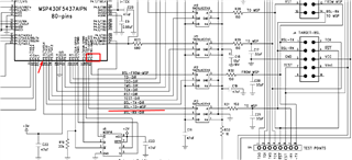
3. I 设置电平转换器 SN74LVC1T45 (REP430F 原理图)、以输出处理信号 B->A 方向 P2.0低电平输出。 有关原理图、请参阅文档 REP430F 用户指南。
4.我连接 FTDI 串行电缆以检查输出,我看不到任何东西。 我无法使用逻辑分析仪、而且它也不注册任何信令。
如果有任何帮助、都会很感激!