请注意,本文内容源自机器翻译,可能存在语法或其它翻译错误,仅供参考。如需获取准确内容,请参阅链接中的英语原文或自行翻译。
器件型号:CC1352P Thread 中讨论的其他器件: SysConfig、 SYSBIOS、 CCStudio、 MSP-FET、 MSP432P401R
我们目前正在 CC1352P 上运行 TI-RTOS 和 TI-Drivers 库、版本如下:
- Code Composer Studio 版本:10.4.0.00006
- TI Clang v1.3.0.LTS
- SimpleLink CC13x2 26x2 SDK 5.20.0.52
- SysConfig 1.8.2
我们有三个主要问题:
- 我们似乎找不到在断言失败时为我们提供调试信息的配置/设置。 调试堆栈为空、所有任务的调用堆栈为空: TI-RTOS .cfg 中是否有一些特定的设置 来保留调试堆栈和任务的调用堆栈?


类似地、在出现硬故障时、我们会看到以下情况(图中未显示:任务的调用栈也为空):
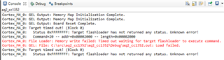
以下是 TI-RTOS 项目中的.cfg 文件:/* * This module contains family specific Boot APIs and configuration settings. * See the SYS/BIOS API guide for more information. */ /* ================ Clock configuration ================ */ var Clock = xdc.useModule('ti.sysbios.knl.Clock'); /* * When using Power and calibrateRCOSC is set to true, this should be set to 10. * The timer used by the Clock module supports TickMode_DYNAMIC. This enables us * to set the tick period to 10 us without generating the overhead of additional * interrupts. * * Note: The calibrateRCOSC parameter is set within the Power configuration * structure in the "Board.c" file. */ Clock.tickPeriod = 1000; /* ================ Defaults (module) configuration ================ */ var Defaults = xdc.useModule('xdc.runtime.Defaults'); /* * A flag to allow module names to be loaded on the target. Module name * strings are placed in the .const section for debugging purposes. * * Pick one: * - true (default) * Setting this parameter to true will include name strings in the .const * section so that Errors and Asserts are easier to debug. * - false * Setting this parameter to false will reduce footprint in the .const * section. As a result, Error and Assert messages will contain an * "unknown module" prefix instead of the actual module name. * * When using BIOS in ROM: * This option must be set to false. */ //Defaults.common$.namedModule = true; Defaults.common$.namedModule = false; /* ================ Error configuration ================ */ //var Error = xdc.useModule('xdc.runtime.Error'); /* * This function is called to handle all raised errors, but unlike * Error.raiseHook, this function is responsible for completely handling the * error with an appropriately initialized Error_Block. * * Pick one: * - Error.policyDefault (default) * Calls Error.raiseHook with an initialized Error_Block structure and logs * the error using the module's logger. * - Error.policySpin * Simple alternative that traps on a while(1) loop for minimized target * footprint. * Using Error.policySpin, the Error.raiseHook will NOT called. * - Error.policyMin * Lightweight policy function that does minimum processing and returns. */ //Error.policyFxn = Error.policyDefault; //Error.policyFxn = Error.policySpin; //Error.policyFxn = Error.policyMin; /* * If Error.policyFxn is set to Error.policyDefault, this function is called * whenever an error is raised by the Error module. * * Pick one: * - Error.print (default) * Errors are formatted and output via System_printf() for easier * debugging. * - null * Errors are not formatted or logged. This option reduces code footprint. * - non-null function * Errors invoke custom user function. See the Error module documentation * for more details. */ //Error.raiseHook = Error.print; //Error.raiseHook = null; //Error.raiseHook = "&myErrorFxn"; /* * If Error.policyFxn is set to Error.policyDefault, this option applies to the * maximum number of times the Error.raiseHook function can be recursively * invoked. This option limits the possibility of an infinite recursion that * could lead to a stack overflow. * The default value is 16. */ //Error.maxDepth = 2; /* ================ Hwi configuration ================ */ var halHwi = xdc.useModule('ti.sysbios.hal.Hwi'); var m3Hwi = xdc.useModule('ti.sysbios.family.arm.m3.Hwi'); /* * Checks for Hwi (system) stack overruns while in the Idle loop. * * Pick one: * - true (default) * Checks the top word for system stack overflows during the idle loop and * raises an Error if one is detected. * - false * Disabling the runtime check improves runtime performance and yields a * reduced flash footprint. */ //halHwi.checkStackFlag = true; halHwi.checkStackFlag = false; /* * The following options alter the system's behavior when a hardware exception * is detected. * * Pick one: * - Hwi.enableException = true * This option causes the default m3Hwi.excHandlerFunc function to fully * decode an exception and dump the registers to the system console. * This option raises errors in the Error module and displays the * exception in ROV. * - Hwi.enableException = false * This option reduces code footprint by not decoding or printing the * exception to the system console. * It however still raises errors in the Error module and displays the * exception in ROV. * - Hwi.excHandlerFunc = null * This is the most aggressive option for code footprint savings; but it * can difficult to debug exceptions. It reduces flash footprint by * plugging in a default while(1) trap when exception occur. This option * does not raise an error with the Error module. */ //m3Hwi.enableException = true; m3Hwi.enableException = false; //m3Hwi.excHandlerFunc = null; /* * Enable hardware exception generation when dividing by zero. * * Pick one: * - 0 (default) * Disables hardware exceptions when dividing by zero * - 1 * Enables hardware exceptions when dividing by zero */ m3Hwi.nvicCCR.DIV_0_TRP = 0; //m3Hwi.nvicCCR.DIV_0_TRP = 1; /* ================ Idle configuration ================ */ var Idle = xdc.useModule('ti.sysbios.knl.Idle'); /* * The Idle module is used to specify a list of functions to be called when no * other tasks are running in the system. * * Functions added here will be run continuously within the idle task. * * Function signature: * Void func(Void); */ //Idle.addFunc("&myIdleFunc"); Idle.addFunc('&Power_idleFunc'); /* add the Power module's idle function */ /* ================ Kernel (SYS/BIOS) configuration ================ */ var BIOS = xdc.useModule('ti.sysbios.BIOS'); /* * Enable asserts in the BIOS library. * * Pick one: * - true (default) * Enables asserts for debugging purposes. * - false * Disables asserts for a reduced code footprint and better performance. * * When using BIOS in ROM: * This option must be set to false. */ //BIOS.assertsEnabled = true; BIOS.assertsEnabled = false; /* * A flag to determine if xdc.runtime sources are to be included in a custom * built BIOS library. * * Pick one: * - false (default) * The pre-built xdc.runtime library is provided by the respective target * used to build the application. * - true * xdc.runtime library sources are to be included in the custom BIOS * library. This option yields the most efficient library in both code * footprint and runtime performance. */ //BIOS.includeXdcRuntime = false; BIOS.includeXdcRuntime = true; /* * The SYS/BIOS runtime is provided in the form of a library that is linked * with the application. Several forms of this library are provided with the * SYS/BIOS product. * * Pick one: * - BIOS.LibType_Custom * Custom built library that is highly optimized for code footprint and * runtime performance. * - BIOS.LibType_Debug * Custom built library that is non-optimized that can be used to * single-step through APIs with a debugger. * */ BIOS.libType = BIOS.LibType_Custom; //BIOS.libType = BIOS.LibType_Debug; /* * Runtime instance creation enable flag. * * Pick one: * - true (default) * Allows Mod_create() and Mod_delete() to be called at runtime which * requires a default heap for dynamic memory allocation. * - false * Reduces code footprint by disallowing Mod_create() and Mod_delete() to * be called at runtime. Object instances are constructed via * Mod_construct() and destructed via Mod_destruct(). * * When using BIOS in ROM: * This option must be set to true. */ BIOS.runtimeCreatesEnabled = true; //BIOS.runtimeCreatesEnabled = false; /* * Enable logs in the BIOS library. * * Pick one: * - true (default) * Enables logs for debugging purposes. * - false * Disables logging for reduced code footprint and improved runtime * performance. * * When using BIOS in ROM: * This option must be set to false. */ //BIOS.logsEnabled = true; BIOS.logsEnabled = false; /* ================ Memory configuration ================ */ var Memory = xdc.useModule('xdc.runtime.Memory'); /* * The Memory module itself simply provides a common interface for any * variety of system and application specific memory management policies * implemented by the IHeap modules(Ex. HeapMem, HeapBuf). */ /* * Use HeapMem primary heap instance to use linker-defined memory region * Add HeapTrack on top to find over-writes, invalid frees, and * aid in finding the correct sizing of the heap and memory leaks. */ var HeapMem = xdc.useModule('ti.sysbios.heaps.HeapMem'); HeapMem.primaryHeapBaseAddr = "&__primary_heap_start__"; HeapMem.primaryHeapEndAddr = "&__primary_heap_end__"; var heapMemParams = new HeapMem.Params(); heapMemParams.usePrimaryHeap = true; //var HeapTrack = xdc.useModule('ti.sysbios.heaps.HeapTrack'); //var heapTrackParams = new HeapTrack.Params; //heapTrackParams.heap = HeapMem.create(heapMemParams); //Program.global.heap0 = HeapTrack.create(heapTrackParams); Program.global.heap0 = HeapMem.create(heapMemParams); Memory.defaultHeapInstance = Program.global.heap0; /* ================ Program configuration ================ */ /* * Program.stack must be set to 0 to allow the setting * of the system stack size to be determined in the example's * linker command file. */ Program.stack = 0; /* * Uncomment to enable Semihosting for GNU targets to print to the CCS console. * Please read the following TIRTOS Wiki page for more information on Semihosting: * processors.wiki.ti.com/.../TI-RTOS_Examples_SemiHosting */ if (Program.build.target.$name.match(/gnu/)) { //var SemiHost = xdc.useModule('ti.sysbios.rts.gnu.SemiHostSupport'); } /* ================ ROM configuration ================ */ /* * To use BIOS in flash, comment out the code block below. */ //var ROM = xdc.useModule('ti.sysbios.rom.ROM'); //ROM.romName = ROM.CC13X2V2; /* ================ Semaphore configuration ================ */ var Semaphore = xdc.useModule('ti.sysbios.knl.Semaphore'); /* * Enables global support for Task priority pend queuing. * * Pick one: * - true (default) * This allows pending tasks to be serviced based on their task priority. * - false * Pending tasks are services based on first in, first out basis. * * When using BIOS in ROM: * This option must be set to false. */ //Semaphore.supportsPriority = true; Semaphore.supportsPriority = false; /* * Allows for the implicit posting of events through the semaphore, * disable for additional code saving. * * Pick one: * - true * This allows the Semaphore module to post semaphores and events * simultaneously. * - false (default) * Events must be explicitly posted to unblock tasks. * * When using BIOS in ROM: * This option must be set to false. */ //Semaphore.supportsEvents = true; Semaphore.supportsEvents = false; /* ================ Swi configuration ================ */ var Swi = xdc.useModule('ti.sysbios.knl.Swi'); /* * A software interrupt is an object that encapsulates a function to be * executed and a priority. Software interrupts are prioritized, preempt tasks * and are preempted by hardware interrupt service routines. * * This module is included to allow Swi's in a users' application. */ /* * Reduce the number of swi priorities from the default of 16. * Decreasing the number of swi priorities yields memory savings. */ Swi.numPriorities = 6; /* ================ System configuration ================ */ var System = xdc.useModule('xdc.runtime.System'); /* * The Abort handler is called when the system exits abnormally. * * Pick one: * - System.abortStd (default) * Call the ANSI C Standard 'abort()' to terminate the application. * - System.abortSpin * A lightweight abort function that loops indefinitely in a while(1) trap * function. * - A custom abort handler * A user-defined function. See the System module documentation for * details. */ //System.abortFxn = System.abortStd; System.abortFxn = System.abortSpin; //System.abortFxn = "&myAbortSystem"; /* * The Exit handler is called when the system exits normally. * * Pick one: * - System.exitStd (default) * Call the ANSI C Standard 'exit()' to terminate the application. * - System.exitSpin * A lightweight exit function that loops indefinitely in a while(1) trap * function. * - A custom exit function * A user-defined function. See the System module documentation for * details. */ //System.exitFxn = System.exitStd; System.exitFxn = System.exitSpin; //System.exitFxn = "&myExitSystem"; /* * Minimize exit handler array in the System module. The System module includes * an array of functions that are registered with System_atexit() which is * called by System_exit(). The default value is 8. */ System.maxAtexitHandlers = 2; /* * Enable System_printf() to display floats. Use the longer '%f%$L%$S%$F' * if your code has SYS/BIOS instrumentation enabled (Asserts/Error/Log), * as is typical with the 'debug' profile. */ //System.extendedFormats = '%f%$L%$S%$F'; System.extendedFormats = '%f%$S'; /* * The System.SupportProxy defines a low-level implementation of System * functions such as System_printf(), System_flush(), etc. * * Pick one pair: * - SysMin * This module maintains an internal configurable circular buffer that * stores the output until System_flush() is called. * The size of the circular buffer is set via SysMin.bufSize. * - SysCallback * SysCallback allows for user-defined implementations for System APIs. * The SysCallback support proxy has a smaller code footprint and can be * used to supply custom System_printf services. * The default SysCallback functions point to stub functions. See the * SysCallback module's documentation. */ var SysMin = xdc.useModule('xdc.runtime.SysMin'); SysMin.bufSize = 1024; System.SupportProxy = SysMin; //var SysCallback = xdc.useModule('xdc.runtime.SysCallback'); //System.SupportProxy = SysCallback; //SysCallback.abortFxn = "&myUserAbort"; //SysCallback.exitFxn = "&myUserExit"; //SysCallback.flushFxn = "&myUserFlush"; //SysCallback.putchFxn = "&myUserPutch"; //SysCallback.readyFxn = "&myUserReady"; /* ================ Task configuration ================ */ var Task = xdc.useModule('ti.sysbios.knl.Task'); /* * Check task stacks for overflow conditions. * * Pick one: * - true (default) * Enables runtime checks for task stack overflow conditions during * context switching ("from" and "to") * - false * Disables runtime checks for task stack overflow conditions. * * When using BIOS in ROM: * This option must be set to false. */ //Task.checkStackFlag = true; Task.checkStackFlag = false; /* * Set the default task stack size when creating tasks. * * The default is dependent on the device being used. Reducing the default stack * size yields greater memory savings. */ Task.defaultStackSize = 512; /* * Enables the idle task. * * Pick one: * - true (default) * Creates a task with priority of 0 which calls idle hook functions. This * option must be set to true to gain power savings provided by the Power * module. * - false * No idle task is created. This option consumes less memory as no * additional default task stack is needed. * To gain power savings by the Power module without having the idle task, * add Idle.run as the Task.allBlockedFunc. */ Task.enableIdleTask = true; //Task.enableIdleTask = false; //Task.allBlockedFunc = Idle.run; /* * If Task.enableIdleTask is set to true, this option sets the idle task's * stack size. * * Reducing the idle stack size yields greater memory savings. */ Task.idleTaskStackSize = 512; /* * Reduce the number of task priorities. * The default is 16. * Decreasing the number of task priorities yield memory savings. */ Task.numPriorities = 16; /* ================ Text configuration ================ */ var Text = xdc.useModule('xdc.runtime.Text'); /* * These strings are placed in the .const section. Setting this parameter to * false will save space in the .const section. Error, Assert and Log messages * will print raw ids and args instead of a formatted message. * * Pick one: * - true (default) * This option loads test string into the .const for easier debugging. * - false * This option reduces the .const footprint. */ //Text.isLoaded = true; Text.isLoaded = false; /* ================ Types configuration ================ */ var Types = xdc.useModule('xdc.runtime.Types'); /* * This module defines basic constants and types used throughout the * xdc.runtime package. */ /* ================ Application Specific Instances ================ */ /* ================ Diagnostics configuration ================ */ //var Diags = xdc.useModule('xdc.runtime.Diags'); /* * You use the Diags module to set and clear bits in a module's diagnostics * mask for the purpose of controlling diagnostics within that module. A * module diagnostics mask controls both Assert and Log statements * within that module, disabling these statements yields * code savings. */ /* ================ Logging configuration ================ */ //var Log = xdc.useModule('xdc.runtime.Log'); /* * Modules and the application code generate Log_Event events by calling * the Log module's functions. * Disabling all Log statements here will allow the optimizer to completely * remove all Log code from the application. * * Note: In order to generate Log events in your application both the Diags * and the Log mask must be set. See the SYS/BIOS API guide for * more information. */ /* * LoggingSetup configures TI-RTOS modules to capture user-specified information * such as CPU Load, Task Load and Task Execution so that it can be * displayed by System Analyzer. */ //var LoggingSetup = xdc.useModule('ti.uia.sysbios.LoggingSetup'); //LoggingSetup.loadLoggerSize = 256; //LoggingSetup.mainLoggerSize = 512; //LoggingSetup.sysbiosLoggerSize = 1024; /* ================ Main configuration ================ */ var Main = xdc.useModule('xdc.runtime.Main'); /* Configuration of this Main module is used for all code not in a module */ /* ================ POSIX configuration ================ */ var Settings = xdc.useModule('ti.posix.tirtos.Settings'); if (Program.build.target.$name.match(/iar/)) { /* * For the IAR target, the 'ti.posix.tirtos.Settings' uses the * MultithreadSupport module. By default, the MultithreadSupport module * use the '--threaded_lib' library which provides a separate 'errno' * per thread and makes other rts libraries reentrant. This library has * a larger footprint which can be a problem for some apps, so we * override the default and disable it here. */ var MultithreadSupport = xdc.useModule('ti.sysbios.rts.iar.MultithreadSupport'); MultithreadSupport.enableMultithreadSupport = false; } /* ================ Event configuration ================ */ var Event = xdc.useModule('ti.sysbios.knl.Event'); /* ================ Mailbox configuration ================ */ var Mailbox = xdc.useModule('ti.sysbios.knl.Mailbox'); - 我们偶尔会遇到闪存和启动调试会话的问题。 通常(并非总是如此)、它将使用用于 SPI 的 TI 驱动程序内的 PC 地址触发硬故障。 在这种情况下、它会经历中止序列、固件会挂起。 但是、如果我们停止调试会话并简单地对器件进行下电上电、我们的固件就可以正常运行而不会挂起。 新的闪存/调试会话是否会导致某些差异?


我们的.syscfg 文件:/** * These arguments were used when this file was generated. They will be automatically applied on subsequent loads * via the GUI or CLI. Run CLI with '--help' for additional information on how to override these arguments. * @cliArgs --device "CC1352P1F3RGZ" --package "RGZ" --part "Default" --product "simplelink_cc13x2_26x2_sdk@5.20.00.52" * @versions {"data":"2021060817","timestamp":"2021060817","tool":"1.8.2+1992","templates":null} */ /** * Import the modules used in this configuration. */ const CCFG = scripting.addModule("/ti/devices/CCFG"); const Board = scripting.addModule("/ti/drivers/Board"); const GPIO = scripting.addModule("/ti/drivers/GPIO"); const GPIO1 = GPIO.addInstance(); const GPIO2 = GPIO.addInstance(); const GPIO3 = GPIO.addInstance(); const GPIO4 = GPIO.addInstance(); const GPIO5 = GPIO.addInstance(); const I2C = scripting.addModule("/ti/drivers/I2C", {}, false); const I2C1 = I2C.addInstance(); const Power = scripting.addModule("/ti/drivers/Power"); const RTOS = scripting.addModule("/ti/drivers/RTOS"); const SPI = scripting.addModule("/ti/drivers/SPI", {}, false); const SPI1 = SPI.addInstance(); const Watchdog = scripting.addModule("/ti/drivers/Watchdog", {}, false); const Watchdog1 = Watchdog.addInstance(); /** * Write custom configuration values to the imported modules. */ CCFG.enableDCDC = false; CCFG.ccfgTemplate.$name = "ti_devices_CCFGTemplate0"; Board.generateInitializationFunctions = false; GPIO1.$name = "GPIO_RS485_TXEN"; GPIO1.gpioPin.$assign = "10"; GPIO1.pinInstance.$name = "CONFIG_PIN_0"; GPIO2.$name = "GPIO_NFC_GPO"; GPIO2.pull = "Pull Up"; GPIO2.interruptTrigger = "Falling Edge"; GPIO2.callbackFunction = "ST25DVXXK_NFC_GPO_Callback"; GPIO2.gpioPin.$assign = "11"; GPIO2.pinInstance.$name = "CONFIG_PIN_1"; GPIO3.$name = "GPIO_OLED_DISPLAY_RS"; GPIO3.mode = "Output"; GPIO3.initialOutputState = "High"; GPIO3.gpioPin.$assign = "14"; GPIO3.pinInstance.$name = "CONFIG_PIN_5"; GPIO4.$name = "GPIO_OLED_DISPLAY_DC"; GPIO4.mode = "Output"; GPIO4.gpioPin.$assign = "15"; GPIO4.pinInstance.$name = "CONFIG_PIN_6"; GPIO5.$name = "GPIO_OLED_DISPLAY_CS"; GPIO5.mode = "Output"; GPIO5.gpioPin.$assign = "32"; GPIO5.pinInstance.$name = "CONFIG_PIN_7"; I2C1.$name = "I2C_MULTI"; I2C1.maxBitRate = 100000; I2C1.i2c.sdaPin.$assign = "30"; I2C1.i2c.sclPin.$assign = "29"; I2C1.sdaPinInstance.$name = "CONFIG_PIN_8"; I2C1.clkPinInstance.$name = "CONFIG_PIN_9"; Power.enablePolicy = false; Power.calibrateRCOSC_HF = false; Power.calibrateRCOSC_LF = false; Power.calibrateFunction = "PowerCC26XX_noCalibrate"; SPI1.minDmaTransferSize = 0; SPI1.$name = "SPI_OLED_DISPLAY"; SPI1.spi.sclkPin.$assign = "28"; SPI1.spi.misoPin.$assign = "43"; SPI1.spi.mosiPin.$assign = "27"; SPI1.sclkPinInstance.$name = "CONFIG_PIN_2"; SPI1.misoPinInstance.$name = "CONFIG_PIN_3"; SPI1.mosiPinInstance.$name = "CONFIG_PIN_4"; Watchdog1.$name = "WATCHDOG"; /** * Pinmux solution for unlocked pins/peripherals. This ensures that minor changes to the automatic solver in a future * version of the tool will not impact the pinmux you originally saw. These lines can be completely deleted in order to * re-solve from scratch. */ I2C1.i2c.$suggestSolution = "I2C0"; SPI1.spi.$suggestSolution = "SSI0"; SPI1.spi.dmaRxChannel.$suggestSolution = "DMA_CH3"; SPI1.spi.dmaTxChannel.$suggestSolution = "DMA_CH4"; Watchdog1.watchdog.$suggestSolution = "WDT0";
我们用于调试的.launch 文件:<?xml version="1.0" encoding="UTF-8" standalone="no"?> <launchConfiguration type="com.ti.ccstudio.debug.launchType.device.debugging"> <stringAttribute key="com.ti.ccstudio.debug.debugModel.ATTR_DEBUGGER_PROPERTIES.CC1352P1F3.ccxml.Texas Instruments XDS110 USB Debug Probe/Cortex_M4_0" value="<?xml version="1.0" encoding="UTF-8" standalone="no" ?> <PropertyValues> <property id="ConnectOnStartup"> <curValue>1</curValue> </property> <property id="EnableInstalledBreakpoint"> <curValue>1</curValue> </property> <property id="IgnoreSoftLaunchFailures"> <curValue>0</curValue> </property> </PropertyValues> "/> <stringAttribute key="com.ti.ccstudio.debug.debugModel.ATTR_PROGRAM.CC1352P1F3.ccxml.Texas Instruments XDS110 USB Debug Probe/Cortex_M4_0" value="${build_artifact:aq2}"/> <stringAttribute key="com.ti.ccstudio.debug.debugModel.ATTR_PROJECT.CC1352P1F3.ccxml.Texas Instruments XDS110 USB Debug Probe/Cortex_M4_0" value="aq2"/> <stringAttribute key="com.ti.ccstudio.debug.debugModel.ATTR_TARGET_CONFIG" value="${target_config_active_default:aq2}"/> <stringAttribute key="com.ti.ccstudio.debug.debugModel.MRU_PROGRAM.CC1352P1F3.ccxml.Texas Instruments XDS110 USB Debug Probe/Cortex_M4_0" value="C:\derrick_workspace\git\aq2_cc13x2\Debug\aq2.out"/> <listAttribute key="org.eclipse.debug.core.MAPPED_RESOURCE_PATHS"> <listEntry value="/aq2"/> </listAttribute> <listAttribute key="org.eclipse.debug.core.MAPPED_RESOURCE_TYPES"> <listEntry value="4"/> </listAttribute> <stringAttribute key="org.eclipse.debug.core.source_locator_id" value="com.ti.ccstudio.debug.sourceLocator"/> <stringAttribute key="org.eclipse.debug.core.source_locator_memento" value="<?xml version="1.0" encoding="UTF-8" standalone="no"?> <sourceLookupDirector> <sourceContainers duplicates="false"> <container memento="<?xml version="1.0" encoding="UTF-8" standalone="no"?> <default/> " typeId="org.eclipse.debug.core.containerType.default"/> <container memento="<?xml version="1.0" encoding="UTF-8" standalone="no"?> <cpuSpecificContainer cpuName="Texas Instruments XDS110 USB Debug Probe/Cortex_M4_0"> <childContainerEntry childMemento="<?xml version="1.0" encoding="UTF-8" standalone="no"?> <project name="aq2" referencedProjects="true"/> " childType="org.eclipse.debug.core.containerType.project"/> <childContainerEntry childMemento="<?xml version="1.0" encoding="UTF-8" standalone="no"?> <default/> " childType="org.eclipse.debug.core.containerType.default"/> <childContainerEntry childMemento="<?xml version="1.0" encoding="UTF-8" standalone="no"?> <productsSource/> " childType="com.ti.ccstudio.debug.containerType.products.source"/> <childContainerEntry childMemento="<?xml version="1.0" encoding="UTF-8" standalone="no"?> <deviceLibrarySource/> " childType="com.ti.ccstudio.debug.containerType.device.library.source"/> <childContainerEntry childMemento="<?xml version="1.0" encoding="UTF-8" standalone="no"?> <librarySource/> " childType="com.ti.ccstudio.debug.containerType.library.source"/> </cpuSpecificContainer> " typeId="com.ti.ccstudio.debug.containerType.cpu.specific"/> </sourceContainers> </sourceLookupDirector> "/> </launchConfiguration> - 调试器尝试连接/闪存时会出现偶发问题、无法判断 事件的顺序导致了该问题或暂时修复了该问题。 我们已经尝试将 JTAG TCLK 频率从5.5MHz 一直降低到2.5MHz、没有任何差异。
以下是我们的.ccxml 目标配置文件:<?xml version="1.0" encoding="UTF-8" standalone="no"?> <configurations XML_version="1.2" id="configurations_0"> <configuration XML_version="1.2" id="configuration_0"> <instance XML_version="1.2" desc="Texas Instruments XDS110 USB Debug Probe" href="connections/TIXDS110_Connection.xml" id="Texas Instruments XDS110 USB Debug Probe" xml="TIXDS110_Connection.xml" xmlpath="connections"/> <connection XML_version="1.2" id="Texas Instruments XDS110 USB Debug Probe"> <instance XML_version="1.2" href="drivers/tixds510icepick_c.xml" id="drivers" xml="tixds510icepick_c.xml" xmlpath="drivers"/> <instance XML_version="1.2" href="drivers/tixds510cs_dap.xml" id="drivers" xml="tixds510cs_dap.xml" xmlpath="drivers"/> <instance XML_version="1.2" href="drivers/tixds510cortexM.xml" id="drivers" xml="tixds510cortexM.xml" xmlpath="drivers"/> <property Type="choicelist" Value="0" id="Power Selection"> <choice Name="Probe supplied power" value="1"> <property Type="stringfield" Value="3.3" id="Voltage Level"/> </choice> </property> <property Type="choicelist" Value="0" id="JTAG Signal Isolation"/> <property Type="choicelist" Value="4" id="SWD Mode Settings"> <choice Name="cJTAG (1149.7) 2-pin advanced modes" value="enable"> <property Type="choicelist" Value="1" id="XDS110 Aux Port"/> </choice> </property> <platform XML_version="1.2" id="platform_0"> <instance XML_version="1.2" desc="CC1352P1F3" href="devices/cc1352p1f3.xml" id="CC1352P1F3" xml="cc1352p1f3.xml" xmlpath="devices"/> </platform> </connection> </configuration> </configurations>