This thread has been locked.

If you have a related question, please click the "Ask a related question" button in the top right corner. The newly created question will be automatically linked to this question.

[参考译文] SK-AM69:处理器-内部论坛

Guru**** 2332530 points
Other Parts Discussed in Thread: SK-AM69, AM68, AM67
请注意,本文内容源自机器翻译,可能存在语法或其它翻译错误,仅供参考。如需获取准确内容,请参阅链接中的英语原文或自行翻译。

https://e2e.ti.com/support/processors-group/processors/f/processors-forum/1478660/sk-am69-processors---internal-forum

器件型号:SK-AM69
Thread 中讨论的其他器件: AM68AM67

工具/软件:

我正在努力以100fps 的速率在 SK-AM69上实现 ov7251。 我们在 SDK 中没有传感器的 dtso 文件、因此我编辑了  k3-j721e-sk-csi2-dual-imx219.dtso 文件、将 ov7251的变量替换为这些变量。 我能够构建 DBS 并将 dtbo 文件和映像复制到 SD 卡、而没有出现任何问题。 但是、每当我启用覆盖电路板时、引导过程似乎都无法完成。  

k3-navss-ringacc ringacc@2b800000:环加速器探测环:286, gp-rings[96,20] sci-dev-id:328
k3-navss-ringacc ringacc@2b800000:dma-ring-reset-quirk:禁用
am65_cpsw_Nuss_port 以太网@46000000port@1:k3 CPSW:rflow_id_base:3.
以太网@46000000port@1等待 PHY 自动协商完成…… 超时!
am65_cpsw_Nuss_port 以太网@46000000port@1:PHY_startup 失败
am65_cpsw_Nuss_port 以太网@46000000port@1:am65_cpsw_start end 错误
am65_cpsw_Nuss_port 以太网@46000000port@1:k3 CPSW:rflow_id_base:3.
以太网@46000000port@1等待 PHY 自动协商完成…… 超时!
am65_cpsw_Nuss_port 以太网@46000000port@1:PHY_startup 失败
am65_cpsw_Nuss_port 以太网@46000000port@1:am65_cpsw_start end 错误
不再有 bootdev
------------------------ ----- ----- -------------------------------- ------------------------
(1个引导流程、1个有效)

创建的 dtso 文件:  

// SPDX-License-Identifier:仅 GPL-2.0-only 或 MIT
/**
*连接 CSI2的双 RPi 摄像头 v2.1 (Omnivision OV7251)的 DT 重叠
*在 J721E SK、AM68 SK 或 AM69-SK 电路板上。
* datasheets.raspberrypi.org/.../camera-v2-schematic.pdf
*
* 2024年版权所有德州仪器(TI)公司- https://www.ti.com/
*/

/dts-v1/;
/plugin/;

#include
#include "k3-pinctrl.h"

&{/}{
CLK_imx219_fixed:ov7251-XCLK{
兼容="固定时钟";
#clock-cells =<0>;
时钟频率=<24000000>;
};
};

&CSI_mux{
空闲状态=<1>;
};

/* CAM00 I2C */
&cam0_i2c{
#address-cells =<1>;
#size-cells =<0>;
ov7251_0:ov7251-0@3c{
兼容="ovti、ov7251";
reg =<0x3c>;

Clocks =<&clk_ov7251_FIXE>;
时钟名称="XCLK";

端口{
csi2_cam0:端点{
远程端点=<&csi2rx0_in_sensor>;
链路频率=/bits/64 <240000000 319200000>;
时钟通道=<1>;
数据通路=<0>;
};
};
};
};

/* CAM1 I2C */
&CAM1_i2c{
#address-cells =<1>;
#size-cells =<0>;
ov7251_1:ov7251-1@3c{
兼容="ovti、ov7251";
reg =<0x3c>;

Clocks =<&clk_ov7251_FIXE>;
时钟名称="XCLK";

端口{
csi2_cam1:端点{
远程端点=<&csi2rx1_in_sensor>;
链路频率=/bits/64 <240000000 319200000>;
时钟通道=<1>;
数据通路=<0>;
};
};
};
};


&cdns_csi2rx0{
端口{
#address-cells =<1>;
#size-cells =<0>;

csi0_port0:port@0{
reg =<0>;
状态="正常";

csi2rx0_in_sensor:端点{
远程端点=<&csi2_cam0>;
总线类型=<4>;/* CSI2 DPHY。 */
时钟通道=<1>;
数据通路=<0>;
};
};

csi0_port1:端口@1{
reg =<1>;
STATUS ="已禁用";
};

csi0_port2:端口@2{
reg =<2>;
STATUS ="已禁用";
};

csi0_port3:端口@3{
reg =<3>;
STATUS ="已禁用";
};

csi0_Port4:端口@4{
reg =<4>;
STATUS ="已禁用";
};
};
};

&dphy0{
状态="正常";
};

&ti_csi2rx0{
状态="正常";
};

&cdns_csi2rx1{
端口{
#address-cells =<1>;
#size-cells =<0>;

csi1_port0:端口@0{
reg =<0>;
状态="正常";

csi2rx1_in_sensor:端点{
远程端点=<&csi2_CAM1>;
总线类型=<4>;/* CSI2 DPHY。 */
时钟通道=<1>;
数据通路=<0>;
};
};

csi1_port1:端口@1{
reg =<1>;
STATUS ="已禁用";
};

csi1_port2:端口@2{
reg =<2>;
STATUS ="已禁用";
};

csi1_port3:端口@3{
reg =<3>;
STATUS ="已禁用";
};

csi1_Port4:端口@4{
reg =<4>;
STATUS ="已禁用";
};
};
};

&dphy1{
状态="正常";
};

&ti_csi2rx1{
状态="正常";
};

  • 请注意,本文内容源自机器翻译,可能存在语法或其它翻译错误,仅供参考。如需获取准确内容,请参阅链接中的英语原文或自行翻译。

    您好:  

    能否以文本文件附件的形式共享成功和失败的日志?

    您能否确认没有 dtbo 引导时一切正常?  

    此致、

    Keerthy  

  • 请注意,本文内容源自机器翻译,可能存在语法或其它翻译错误,仅供参考。如需获取准确内容,请参阅链接中的英语原文或自行翻译。

    是的、我可以确认在没有启用 dtbo 的情况下可以启动。 我将在此处附上文件。

  • 请注意,本文内容源自机器翻译,可能存在语法或其它翻译错误,仅供参考。如需获取准确内容,请参阅链接中的英语原文或自行翻译。

    您好、

    fdt_overlay_apply 失败、请尝试使用默认的 dtbo、而不进行编辑、这应该会起作用。 然后尝试检查哪些修改导致叠加失败。

    此致、

    Keerthy  

  • 请注意,本文内容源自机器翻译,可能存在语法或其它翻译错误,仅供参考。如需获取准确内容,请参阅链接中的英语原文或自行翻译。

    尊敬的 Dhane:

    是否可以尝试将所有链路频率实例更改为以下内容?

    链路频率=/bits/64 <456000000>;

    谢谢您、

    法比亚纳

  • 请注意,本文内容源自机器翻译,可能存在语法或其它翻译错误,仅供参考。如需获取准确内容,请参阅链接中的英语原文或自行翻译。

    您好:  

    我做了此更改并运行了命令 v4l2-ctl --list-devices、但无法连接到相机。

    此致、

  • 请注意,本文内容源自机器翻译,可能存在语法或其它翻译错误,仅供参考。如需获取准确内容,请参阅链接中的英语原文或自行翻译。

    尊敬的 Dhane:

    传感器是否被探测? 请使用此常见问题解答作为参考、从#1开始。

    [常见问题解答]在 AM6x -处理器论坛-处理器论坛- TI E2E 支持论坛上开发摄像头应用时遇到的最常见问题

    谢谢您、

    法比亚纳

  • 请注意,本文内容源自机器翻译,可能存在语法或其它翻译错误,仅供参考。如需获取准确内容,请参阅链接中的英语原文或自行翻译。

    我相信传感器是被探测的。  
     返回 dmesg | grep csi 命令
    [ 1.393463] i2c 7-003c:固定依赖周期、/bus@10000/ticsi2rx@4500000/csi-bridge@4504000
    [ 1.408068] i2c 8-003c:固定依赖周期、/bus@1000000/ticsi2rx@4510000/CSI-BRIDGE@4514000

  • 请注意,本文内容源自机器翻译,可能存在语法或其它翻译错误,仅供参考。如需获取准确内容,请参阅链接中的英语原文或自行翻译。

      v4l2-ctl --list-devices 命令返回:

    无法打开设备/dev/video0、正在退出  

  • 请注意,本文内容源自机器翻译,可能存在语法或其它翻译错误,仅供参考。如需获取准确内容,请参阅链接中的英语原文或自行翻译。

    尊敬的 Dhane:

    您是否已添加传感器模块(ov7251.ko)? 帧 modprobe ov7251. 如果您还没有这样做。

    请参阅: https://software-dl.ti.com/jacinto7/esd/processor-sdk-linux-am69a/10_01_00/exports/docs/linux/Foundational_Components_Kernel_Users_Guide cloud.html#编译-the-kernel-modules

    谢谢您、

    法比亚纳

  • 请注意,本文内容源自机器翻译,可能存在语法或其它翻译错误,仅供参考。如需获取准确内容,请参阅链接中的英语原文或自行翻译。

    我已经完成了这项工作、现在我能够看到探测到的传感器。

    按照 am67使用摄像头 Academy 中的说明进行操作。
    https://dev.ti.com/tirex/explore/node?fullTextSearch=am67%20use%20camera&fullTextSearchPage=1&node=A__AR3wevo2133UK-QLr4RUgQ__AM67-ACADEMY__XufTZAH__LATEST

    对 media0和 media 运行# media-ctl -d /dev/media0 -p 命令、我无法看到任何链接。 我相信我已正确连接摄像头。 我还需要设置什么内容、还是需要其他方法来检查功能并验证帧速率?


    此致、

  • 请注意,本文内容源自机器翻译,可能存在语法或其它翻译错误,仅供参考。如需获取准确内容,请参阅链接中的英语原文或自行翻译。

    尊敬的 Dhane:

    很高兴听到! 接下来、您需要使用配置媒体图形 media-ctl 。 该 Academy 以及以下常见问题解答中都提到了该问题解答: https://e2e.ti.com/support/processors-group/processors/f/processors-forum/1403218/faq-what-are-the-common-reasons-v4l2-based-applications-fail-to-capture-images-from-a-probed-csi-sensor

    谢谢您、

    法比亚纳

  • 请注意,本文内容源自机器翻译,可能存在语法或其它翻译错误,仅供参考。如需获取准确内容,请参阅链接中的英语原文或自行翻译。

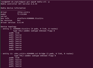
    在这里的所有示例中、我看到 media-ctl 命令存在链接和 routs。 当我运行 media-ctl -p 命令时、结果就是这样

    浏览常见问题和学院,我试图运行 media-ctl -R 命令来设置路由,但不断收到无效参数错误。
    按照这里的示例、我尝试运行 v4l2-ctl -d /dev/media0 --list-subdev-mbus-codes pad=0

    但返回的结果无法检测到/dev/media0正在退出哪个器件。

  • 请注意,本文内容源自机器翻译,可能存在语法或其它翻译错误,仅供参考。如需获取准确内容,请参阅链接中的英语原文或自行翻译。

    尊敬的 Dhane:

    您能尝试将传感器连接到另一个 CSI 端口吗?

    谢谢您、

    法比亚纳

  • 请注意,本文内容源自机器翻译,可能存在语法或其它翻译错误,仅供参考。如需获取准确内容,请参阅链接中的英语原文或自行翻译。

    这产生了相同的结果。  

  • 请注意,本文内容源自机器翻译,可能存在语法或其它翻译错误,仅供参考。如需获取准确内容,请参阅链接中的英语原文或自行翻译。

    尊敬的 Dhane:

    您能否分享您正在运行的命令和生成的日志? 如果您也能共享的输出、我将很有帮助  dmesg | grep csi  和  dmesg | grep ov7251 ? 是否确保每次引导时探测传感器模块?

    谢谢您、

    法比亚纳

  • 请注意,本文内容源自机器翻译,可能存在语法或其它翻译错误,仅供参考。如需获取准确内容,请参阅链接中的英语原文或自行翻译。

    您好:

    Root@AM69-sk:~# dmesg | grep csi                                                                                                                                                                                 
    [   1.389561] i2c 7-003c:固定依赖周期、/bus@1000000/ticsi2rx@4500000/csi-bridge@4504000
    [   1.404159] i2c 8-003c:固定依赖周期、其中/bus@10000/ticsi2rx@4510000/csi-bridge@4514000
    [   9.818110] i2c 7-003c:固定依赖周期、/bus@10000/ticsi2rx@4500000/csi-bridge@4504000
    [   9.818173] platform 4504000.csi-bridge:固定依赖周期(s)、其中/bus@10000/i2c@2010000/i2c-mux@70/i2c@0/ov7251-0@3c
    [   9.854322] i2c 8-003c:固定依赖周期、/bus@10000/ticsi2rx@4510000/CSI-BRIDGE@4514000
    [   9.854381] platform 4514000.csi-bridge:具有/bus@10000/i2c@2010000/i2c-mux@70/i2c@1/ov7251-1@3c 的固定依赖周期
    [   9.894478] CDNs-csi2rx 4504000.csi-bridge:探测到具有1/4通道、4个流和外部 D-PHY 的 CSI2RX
    [   9.908062] CDN - csi2rx 4514000.CSI 桥接器:探测了具有1/4通道、4个流和外部 D-PHY 的 CSI2RX

    即使在运行 modprobe 命令之后、dmesg | grep ov7251也不会返回任何内容。

  • 请注意,本文内容源自机器翻译,可能存在语法或其它翻译错误,仅供参考。如需获取准确内容,请参阅链接中的英语原文或自行翻译。

    尊敬的 Dhane:

    以下消息指示 CSI2-RX 接口 被探测:

    cdns-csi2rx 4504000.csi-bridge: Probed CSI2RX with 1/4 lanes, 4 streams, external D-PHY
    cdns-csi2rx 4514000.csi-bridge: Probed CSI2RX with 1/4 lanes, 4 streams, external D-PHY

    以下消息指示 A 传感器 、ox05b1s 在本 例中已被探测到:

    root@j722s-evm:/opt/edgeai-gst-apps# dmesg | grep ox05b
    ox05b 5-0036: ox05b_detect: detected chip ID 0x0558
    ox05b 5-0036: ox05b1s probed!

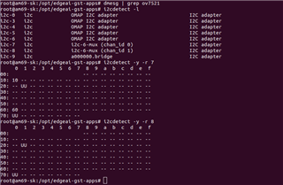
    请回到 此常见问题解答 的第2部分、在验证传感器连接是否正确后分享 i2cdetect 命令的输出。 带状电缆上的引脚应始终朝上。

    谢谢您、

    法比亚纳

  • 请注意,本文内容源自机器翻译,可能存在语法或其它翻译错误,仅供参考。如需获取准确内容,请参阅链接中的英语原文或自行翻译。

  • 请注意,本文内容源自机器翻译,可能存在语法或其它翻译错误,仅供参考。如需获取准确内容,请参阅链接中的英语原文或自行翻译。

    尊敬的 Dhane:

    感谢您提供数据。 请允许我花一些时间回顾传感器驱动程序和叠加。

    谢谢、

    法比亚纳

  • 请注意,本文内容源自机器翻译,可能存在语法或其它翻译错误,仅供参考。如需获取准确内容,请参阅链接中的英语原文或自行翻译。

    尊敬的 Fabiana:

    您能否在此处为我提供有关 ETA 的更新、以获得支持?

    此致、

  • 请注意,本文内容源自机器翻译,可能存在语法或其它翻译错误,仅供参考。如需获取准确内容,请参阅链接中的英语原文或自行翻译。

    尊敬的 Dhane:

    请期待本周晚些时候得到我的答复。 感谢您的耐心。

    -法比亚纳

  • 请注意,本文内容源自机器翻译,可能存在语法或其它翻译错误,仅供参考。如需获取准确内容,请参阅链接中的英语原文或自行翻译。

    尊敬的 Dhane:

    感谢您在这个问题上的耐心。 我们可以为明天或下周设置一个快速电话、以便查看您的硬件设置、但在此之前、我希望您确认这不是您使用的带状电缆的问题。 如果您可以使用 imx219传感器、我建议您使用与 ov7251相同的带状电缆来启用它。 如果不方便使用 imx219、请尝试为 ov7251使用不同的带状电缆。

    您将发现的输出  dmesg | grep csi 只要在 uEnv.txt 中启用了相应的覆盖功能、无论传感器是否物理连接、都是相同的。

    谢谢您、

    法比亚纳

  • 请注意,本文内容源自机器翻译,可能存在语法或其它翻译错误,仅供参考。如需获取准确内容,请参阅链接中的英语原文或自行翻译。

    您好:

    我可以尝试使用不同的带状电缆、但仍然遇到相同的问题。 我可以在本周或下周的日历上留出一些时间吗?

    此致、

  • 请注意,本文内容源自机器翻译,可能存在语法或其它翻译错误,仅供参考。如需获取准确内容,请参阅链接中的英语原文或自行翻译。

    尊敬的 Dhane:

    我不会再让她失望的,我不会再让她失望的。」 我浏览了这一主题、分享了我对如何推进调试的想法。

    首先、ov7251.c 摄像头驱动程序的第1526行有一个"dev_info"、该信息应在启动期间打印出来。 如果这不是打印出来,那么我认为 ov7251内核驱动程序没有被正确探测: https://git.ti.com/cgit/ti-linux-kernel/ti-linux-kernel/tree/drivers/media/i2c/ov7251.c?h=ti-linux-6.1.y#n1505

    自从上次从 dmesg 共享日志以来已经有一段时间了、但是您能否再次重新共享完整的"dmesg"日志以查看 ov7251相关日志是否正在打印?

    此致、

    Takuma

  • 请注意,本文内容源自机器翻译,可能存在语法或其它翻译错误,仅供参考。如需获取准确内容,请参阅链接中的英语原文或自行翻译。

    尊敬的 Dhane:

    摄像头驱动程序似乎出现故障:

    [ 9.732248] ov7251 7-003c:错误-EINVAL:未找到支持的链路频率
    [9.732259] ov7251:7-003c 探测器失败、错误为-22

    这就是摄像头输出很可能发生故障的原因。 我没有太深入地查看 ov7251的摄像头驱动程序代码,但有任何猜测为什么这可能是打印出来?

    此致、

    Takuma

  • 请注意,本文内容源自机器翻译,可能存在语法或其它翻译错误,仅供参考。如需获取准确内容,请参阅链接中的英语原文或自行翻译。

    似乎是由于链路频率而产生的误差。  我更改了它以匹配驱动程序文件中的内容、但它似乎仍然失败。

    root@am69-sk:/opt/edgeai-gst-apps# dmesg | grep ov7251
    [    9.728841] ov7251 7-003c: supply vdddo not found, using dummy regulator
    [    9.735481] ov7251 7-003c: supply vddd not found, using dummy regulator
    [    9.735562] ov7251 7-003c: supply vdda not found, using dummy regulator
    [    9.735608] ov7251 7-003c: cannot get enable gpio
    [    9.736079] ov7251: probe of 7-003c failed with error -2
    [    9.736695] ov7251 8-003c: supply vdddo not found, using dummy regulator
    [    9.736796] ov7251 8-003c: supply vddd not found, using dummy regulator
    [    9.736829] ov7251 8-003c: supply vdda not found, using dummy regulator
    [    9.736862] ov7251 8-003c: cannot get enable gpio
    [    9.739873] ov7251: probe of 8-003c failed with error -2
    [    9.850409] platform 4504000.csi-bridge: Fixed dependency cycle(s) with /bus@100000/i2c@2010000/i2c-mux@70/i2c@0/ov7251-0@3c
    [    9.869953] platform 4514000.csi-bridge: Fixed dependency cycle(s) with /bus@100000/i2c@2010000/i2c-mux@70/i2c@1/ov7251-1@3c
    

  • 请注意,本文内容源自机器翻译,可能存在语法或其它翻译错误,仅供参考。如需获取准确内容,请参阅链接中的英语原文或自行翻译。

    尊敬的 Dhane:

    看起来 做的任何更改都 很好。 探测器看起来进展得更远、但出现故障、并显示不同的错误:

    [ 9.735608] ov7251 7-003c:无法获取启用 GPIO
    [9.736079] ov7251:7-003c 探测失败、出现错误-2

    具体而言、驱动程序中的第1678行: https://git.ti.com/cgit/ti-linux-kernel/ti-linux-kernel/tree/drivers/media/i2c/ov7251.c?h=ti-linux-6.6.y#n1678

    我不将其视为器件树绑定中的必需属性、而是查看驱动程序代码、显然需要: https://git.ti.com/cgit/ti-linux-kernel/ti-linux-kernel/tree/Documentation/devicetree/bindings/media/i2c/ovti,ov7251.yaml?h=ti-linux-6.6.y

    此致、

    Takuma

  • 请注意,本文内容源自机器翻译,可能存在语法或其它翻译错误,仅供参考。如需获取准确内容,请参阅链接中的英语原文或自行翻译。

    我尝试将使能 GPIO 行添加到 dtso 文件、但这返回了错误、无法引导。

    对此处的解决方案有何建议?

    此致、

    Dhane Jones

    /* CAM0 I2C */
    &cam0_i2c {
    	#address-cells = <1>;
    	#size-cells = <0>;
    	ov7251_0: ov7251-0@3c {
    		compatible = "ovti,ov7251";
    		reg = <0x3c>;
    
    		clocks = <&clk_ov7251_fixed>;
    		clock-names = "xclk";
    		enable-gpios = <&gpio1 19 GPIO_ACTIVE_HIGH>;
    
    		port {
    			csi2_cam0: endpoint {
    				remote-endpoint = <&csi2rx0_in_sensor>;
    				link-frequencies = /bits/ 64 <240000000 319200000>;
    				clock-lanes = <1>;
    				data-lanes = <0>;
    			};
    		};
    	};
    };
    
    /* CAM1 I2C */
    &cam1_i2c {
    	#address-cells = <1>;
    	#size-cells = <0>;
    	ov7251_1: ov7251-1@3c {
    		compatible = "ovti,ov7251";
    		reg = <0x3c>;
    
    		clocks = <&clk_ov7251_fixed>;
    		clock-names = "xclk";
    		enable-gpios = <&gpio1 19 GPIO_ACTIVE_HIGH>;
    
    		port {
    			csi2_cam1: endpoint {
    				remote-endpoint = <&csi2rx1_in_sensor>;
    				link-frequencies = /bits/ 64 <240000000 319200000>;
    				clock-lanes = <1>;
    				data-lanes = <0>;
    			};
    		};
    	};
    };
    
    U-Boot 2024.04-ti-ga970f6e51043 (Nov 13 2024 - 14:26:23 +0000)
    
    SoC:   J784S4 SR1.0 HS-FS
    Model: Texas Instruments AM69 SK
    DRAM:  2 GiB (effective 32 GiB)
    idle-statesCore:  122 devices, 32 uclasses, devicetree: separate
    Flash: 0 Bytes
    MMC:   mmc@4f80000: 0, mmc@4fb0000: 1
    Loading Environment from nowhere... OK
    In:    serial@2880000
    Out:   serial@2880000
    Err:   serial@2880000
    am65_cpsw_nuss ethernet@46000000: K3 CPSW: nuss_ver: 0x6BA02102 cpsw_ver: 0x6BA82102 ale_ver: 0x00293904 Ports:1
    Net:   eth0: ethernet@46000000port@1
    Hit any key to stop autoboot:  0 
    switch to partitions #0, OK
    mmc1 is current device
    SD/MMC found on device 1
    1139 bytes read in 81 ms (13.7 KiB/s)
    Loaded env from uEnv.txt
    Importing environment from mmc1 ...
    Running uenvcmd ...
    GPIO: 'gpio@22_17' not found
    Command 'gpio' failed: Error -22
    GPIO: 'gpio@22_16' not found
    Command 'gpio' failed: Error -22
    k3_r5f_rproc r5f@41000000: Core 1 is already in use. No rproc commands work
    k3_r5f_rproc r5f@41400000: Core 2 is already in use. No rproc commands work
    499240 bytes read in 208 ms (2.3 MiB/s)
    Warning: Did not detect image signing certificate. Skipping authentication to prevent boot failure. This will fail on Security Enforcing(HS-SE) devices
    Load Remote Processor 2 with data@addr=0x82000000 499240 bytes: Success!
    330996 bytes read in 207 ms (1.5 MiB/s)
    Warning: Did not detect image signing certificate. Skipping authentication to prevent boot failure. This will fail on Security Enforcing(HS-SE) devices
    Load Remote Processor 3 with data@addr=0x82000000 330996 bytes: Success!
    154848 bytes read in 205 ms (737.3 KiB/s)
    Warning: Did not detect image signing certificate. Skipping authentication to prevent boot failure. This will fail on Security Enforcing(HS-SE) devices
    Load Remote Processor 4 with data@addr=0x82000000 154848 bytes: Success!
    154848 bytes read in 205 ms (737.3 KiB/s)
    Warning: Did not detect image signing certificate. Skipping authentication to prevent boot failure. This will fail on Security Enforcing(HS-SE) devices
    Load Remote Processor 5 with data@addr=0x82000000 154848 bytes: Success!
    498940 bytes read in 208 ms (2.3 MiB/s)
    Warning: Did not detect image signing certificate. Skipping authentication to prevent boot failure. This will fail on Security Enforcing(HS-SE) devices
    Load Remote Processor 6 with data@addr=0x82000000 498940 bytes: Success!
    154848 bytes read in 206 ms (733.4 KiB/s)
    Warning: Did not detect image signing certificate. Skipping authentication to prevent boot failure. This will fail on Security Enforcing(HS-SE) devices
    Load Remote Processor 7 with data@addr=0x82000000 154848 bytes: Success!
    14283024 bytes read in 265 ms (51.4 MiB/s)
    Warning: Did not detect image signing certificate. Skipping authentication to prevent boot failure. This will fail on Security Enforcing(HS-SE) devices
    Load Remote Processor 8 with data@addr=0x82000000 14283024 bytes: Success!
    14684488 bytes read in 270 ms (51.9 MiB/s)
    Warning: Did not detect image signing certificate. Skipping authentication to prevent boot failure. This will fail on Security Enforcing(HS-SE) devices
    Load Remote Processor 9 with data@addr=0x82000000 14684488 bytes: Success!
    14283136 bytes read in 265 ms (51.4 MiB/s)
    Warning: Did not detect image signing certificate. Skipping authentication to prevent boot failure. This will fail on Security Enforcing(HS-SE) devices
    Load Remote Processor 10 with data@addr=0x82000000 14283136 bytes: Success!
    14283136 bytes read in 265 ms (51.4 MiB/s)
    Warning: Did not detect image signing certificate. Skipping authentication to prevent boot failure. This will fail on Security Enforcing(HS-SE) devices
    Load Remote Processor 11 with data@addr=0x82000000 14283136 bytes: Success!
    21029376 bytes read in 352 ms (57 MiB/s)
    123583 bytes read in 85 ms (1.4 MiB/s)
    Working FDT set to 88000000
    4818 bytes read in 84 ms (55.7 KiB/s)
    failed on fdt_overlay_apply(): FDT_ERR_NOTFOUND
    Failed to load '/boot/dtb/ti/k3-j784s4-edgai-apps.dtbo'
    ERROR: Did not find a cmdline Flattened Device Tree
    Could not find a valid device tree
    Scanning for bootflows in all bootdevs
    Seq  Method       State   Uclass    Part  Name                      Filename
    ---  -----------  ------  --------  ----  ------------------------  ----------------
    Scanning global bootmeth 'efi_mgr':
    No EFI system partition
    No EFI system partition
    Failed to persist EFI variables
    No EFI system partition
    Failed to persist EFI variables
    No EFI system partition
    Failed to persist EFI variables
    No EFI system partition
    Failed to persist EFI variables
    No EFI system partition
    Failed to persist EFI variables
      0  efi_mgr      ready   (none)       0  <NULL>                    
    ** Booting bootflow '<NULL>' with efi_mgr
    Loading Boot0000 'mmc 1' failed
    Loading Boot0001 'mmc 0' failed
    EFI boot manager: Cannot load any image
    Boot failed (err=-14)
    Scanning bootdev 'mmc@4fb0000.bootdev':
    Scanning bootdev 'mmc@4f80000.bootdev':
    Bus usb@6000000: cdns-usb3-host usb@6000000: Couldn't get USB3 PHY:  -22
    probe failed, error -22
    No working controllers found
    k3-navss-ringacc ringacc@2b800000: Ring Accelerator probed rings:286, gp-rings[96,20] sci-dev-id:328
    k3-navss-ringacc ringacc@2b800000: dma-ring-reset-quirk: disabled
    am65_cpsw_nuss_port ethernet@46000000port@1: K3 CPSW: rflow_id_base: 3
    ethernet@46000000port@1 Waiting for PHY auto negotiation to complete......... TIMEOUT !
    am65_cpsw_nuss_port ethernet@46000000port@1: phy_startup failed
    am65_cpsw_nuss_port ethernet@46000000port@1: am65_cpsw_start end error
    No more bootdevs
    

  • 请注意,本文内容源自机器翻译,可能存在语法或其它翻译错误,仅供参考。如需获取准确内容,请参阅链接中的英语原文或自行翻译。

    尊敬的 Dhane:

    可能再次出现器件树问题、与该主题中的原始帖子类似。

    不确定从哪里获得 GPIO1 19、但可能 ov7251的使能引脚与 imx219的复位引脚相同、但调用方式不同? 我在 imx219.yaml 绑定中看到以下说明。

      reset-gpios:
        maxItems: 1
        description: |-
          Reference to the GPIO connected to the xclr pin, if any.
          Must be released (set high) after all supplies are applied.

    我可以 理解、编写 ov7251驱动程序的开发人员是否可以将此引脚称为使能引脚。

    此致、

    Takuma