This thread has been locked.
If you have a related question, please click the "Ask a related question" button in the top right corner. The newly created question will be automatically linked to this question.
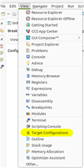
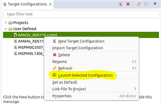
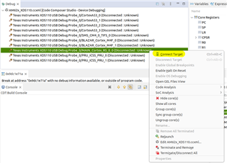
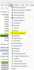
我正在尝试在使用 SDK 9.0+的 AM62x/AM62A/AM62P 器件上将深度睡眠用作低功耗模式。 我们如何使用 SYSFW 跟踪调试深度睡眠?
我们从哪里着手?
TISCI API 将跟踪进出 DM 固件的消息事务并转储一系列具有代表性的十六进制值。 这些十六进制值不是人类可读的形式、因此 SYSFW 跟踪分析器脚本有助于转换十六进制值。
DM 固件在 R5F 内核上运行、因此可在 WKUP UART 端口(/dev/ttyUSB2)上找到事务。
SYSFW 跟踪分析器脚本可以在以下位置找到:
<SDK Install Directory>/bin/sysfw_trace_parser.py
在使用解析器之前、需要执行以下步骤来启用 SYSFW 跟踪、以包含电源管理及其各自的 LPM 序列:
1.修改电路板配置文件
2.修改固件驱动程序 ti_sci.c
3.添加唤醒源的器件树覆盖图(可选、具体取决于唤醒源)
更改电路板配置文件
电路板配置文件的路径:
<SDK Install Directory>/board-support/ti-u-boot-<version>/board/ti/<am62x/am62ax/am62px>/board-cfg.yaml
需要对 board-cfg.YAML 文件进行的更改:
diff --git a/board/ti/am62x/board-cfg.yaml b/board/ti/am62x/board-cfg.yaml index a26ef55bd45b..d9bfbdbb480e 100644 --- a/board/ti/am62x/board-cfg.yaml +++ b/board/ti/am62x/board-cfg.yaml @@ -32,5 +32,5 @@ board-cfg: subhdr: magic: 0x020C size: 8 - trace_dst_enables : 0x00 - trace_src_enables : 0x00 + trace_dst_enables : 0x0d + trace_src_enables : 0x3f
现在、无需在 U-Boot 端进行更多的更改。 按照以下指令进行 Re 构建 U-Boot:
确保复制目标图像。
修改 ti_sci.c
ti_sci.c 的路径:
<SDK Install Directory>/board-support/ti-linux-kernel-<version>/drivers/firmware/ti_sci.c
需要进行的更改:
diff --git a/drivers/firmware/ti_sci.c b/drivers/firmware/ti_sci.c index 8e03488ccc5f..be9ed728044f 100644 --- a/drivers/firmware/ti_sci.c +++ b/drivers/firmware/ti_sci.c @@ -1881,6 +1881,9 @@ static int ti_sci_cmd_set_io_isolation(const struct ti_sci_handle *handle, struct device *dev; int ret = 0; + /*HACK: return without doing anything; required for Sysfw LPM trace */ + return ret; + if (IS_ERR(handle)) return PTR_ERR(handle); if (!handle)
请注意、修改 IO_isolation 代码会影响使用 IO 菊花链的任何唤醒源(如主域 UART)的功能。 有关更多信息、请参阅 TRM 的第6.2.4.11节 I/O 电源管理和菊花链: https://www.ti.com/lit/ug/spruiv7b/spruiv7b.pdf。
现在、需要按照以下指令重新编译映像:
确保复制新映像。
添加唤醒源的器件树覆盖
请查看有关添加每个器件都相同的器件树叠的文档: https://software-dl.ti.com/processor-sdk-linux/esd/AM62X/09_01_00_08/exports/docs/linux/How_to_Guides/Target/How_to_enable_DT_overlays_in_linux.html
在 boot/uEnv.txt 下、添加此行:
name_overlays=k3-am62x-sk-lpm-wkup-sources.dtbo
请注意、在 SDK 的后续版本中、覆盖文件名称可能会发生变化。
生成日志和运行分析程序脚本
使用所做的新更改启动器件。 要隔离与深度睡眠相关的日志、仅在进入深度睡眠之前开始运行解析器脚本。
在 EVM 终端上、让它准备好进入深度睡眠状态。
root@am62xx-evm:~# echo mem > /sys/power/state
在主机终端上、设置脚本:
HOST:~$ cd <SDK Install Directory>/bin HOST:~$ python3 sysfw_trace_parser.py -d /dev/ttyUSB2 -o <output file> -Tv <version> ###For this example, this command was ran: HOST:~$ python3 sysfw_trace_parser.py -d /dev/ttyUSB2 -o am62x_deepsleep_9.1.txt -Tv 0x03007
在两个终端都准备就绪后、运行解析器脚本、然后运行深度睡眠命令。 设备唤醒后、向解析器脚本发送键盘中断(Ctrl + C)。 人类可读的日志将位于指定的输出文件中。
或者、解析器脚本可以将日志输出直接写入终端:
HOST:~$ python3 sysfw_trace_parser.py -d /dev/ttyUSB2 -O -Tv 0x03007
有时解析器会导致错误:
invalid literal for int() with base 16: '0x6C001700H0x6C001820'
解决方法是直接从/dev/ttyUSB2复制日志并将其另存为输入文件。 错误是十六进制值未创建新行引起的。
然后使用输入文件(而不是/dev/ttyUSB2)运行解析器脚本、并选择首选的输出方法:
HOST:~$ python3 sysfw_trace_parser.py -l <input hex log file> -o <output file> -Tv 0x03007 HOST:~$ python3 sysfw_trace_parser.py -l <input hex log file> -O -Tv 0x03007
如何解释日志
每个操作 ID 意味着什么?
电源管理: https://software-dl.ti.com/tisci/esd/latest/4_trace/trace.html#power-management-action-ids
每个时钟 ID 是什么意思?
时钟 ID: https://software-dl.ti.com/tisci/esd/latest/5_soc_doc/am62x/clocks.html#clocks-for-board0-device
器件 ID: https://downloads.ti.com/tisci/esd/latest/5_soc_doc/am62x/devices.html#enumeration-of-device-ids
每个主机 ID 都是什么意思?
主机 ID: https://downloads.ti.com/tisci/esd/latest/5_soc_doc/am62x/hosts.html#enumeration-of-host-ids
其他 ID 可在以下位置找到: https://downloads.ti.com/tisci/esd/latest/5_soc_doc/index.html#am62x
但如果我们无法访问 WKUP UART 端口怎么办?
从 TSCI 固件版本9.1开始、日志的副本存储在 R5F 的 TCMA (ATCM)中。 日志可以在 TCMA 的0x7800地址处找到、并存储在8位十六进制值中。
这些日志并不像 WKUP UART 方法那样完整、但会显示 PM_LPM_SEQ 的关键组件。
完成这些步骤需要用到 Code Composer Studio。
MCU+ SDK 和 Code Composer Studio (CCS)设置
安装 MCU+ SDK 不是必需的、但可能会很有用。
此时、CCS 应该可以运行了。 下一步是运行深度睡眠、以便将日志存储在 R5F 的 TCMA 中。
在 Linux 终端中运行深度睡眠模式
root@am62xx-evm:~# echo mem > /sys/power/state
这应该适用于任何其他低功耗模式。
现在应该不需要对 Linux 终端有任何其他需求。
现在、我们可以连接 R5F 内核并读取存储器。
连接到 R5F 内核
确保器件已引导并且可以访问 Linux 终端(任何方法都应该有效)。
在 CCS 中、通过 Target Configurations 连接到目标:
为使用的器件选择目标配置。 右键点击并选择 Launch Selected Configuration:
让内核加载。 然后在 Debug 下、连接到 Texas Instruments XDS110 USB Debug Probe_0/MAIN_Cortex_R5_0_0:
由于 CCS 连接到 R5F 内核、因此您会注意到 Linux 终端中将出现如下所示的时钟错误:
cpu cpu0: _opp_config_clk_single: failed to set clock rate: -22 cpufreq: __target_index: Failed to change cpu frequency: -22 ti-sci 44043000.system-controller: Mbox timedout in resp(caller: sci_clk_determine_rate+0x64/0xe4) ti-sci 44043000.system-controller: Mbox send fail -110
如果 CSS 断开连接、则错误将停止。
打开内存浏览器:
在内存浏览器中、将地址设置为0x7800、将输出类型设置为字符。
然后、您将看到8位十六进制值。 每个值以0x 开头、并以两个周期隔开。 这些是我们要查找的日志。
为解析器设置输入文件
现在十六进制值已经存在、需要将它们解析为人类可读的形式。
将每个值从存储器浏览器复制到文本文件等文件中并在值之间设置新行。 确保文件中不存在制表符。
下面的示例:
0x6C000100 0x6C000200 0x6C000400 0x6C007700 0x6C000500 0x6C000600 0x6C000700 0x6C000800 0x6C000900 0x6C000A00 0x6C000B00 0x6C000C00 0x6C000D00 0x6C000E00 0x6C000F00 0x6C001000 0x6C001100 0x6C001200 0x6C001300 0x6C001400 0x6C001500 0x6C001600 0x6C001700 0x6C001830 0x6C001900 0x6C001A00 0x6C001B00 0x6C001C00 0x6C001D00 0x6C001E00 0x6C001F00 0x6C002000 0x6C002500 0x6C003300 0x6C003400 0x6C002600 0x6C002700 0x6C002800 0x6C002900 0x6C002A00 0x6C002B00 0x6C002C00 0x6C002D00 0x6C002E00
使用新文件运行分析程序
在主机上:
HOST$ cd <SDK install directory>/bin HOST$ python3 sysfw_trace_parser.py -l <Logs from CCS> -o <Output File> -Tv <Version> ### Or print into the console HOST$ python3 sysfw_trace_parser.py -l <Logs from CCS> -O -Tv <Version>
AM62x 睡眠序列和使用 R5F 的 TCMA 唤醒的采样输出
Configuring trace data version to: 0x03007 0x6C000100: Power Management: PM_LPM_SEQ(Low power mode sequence): DM stub started Value: 0 0x6C000200: Power Management: PM_LPM_SEQ(Low power mode sequence): Unlocked MMRs Value: 0 0x6C000400: Power Management: PM_LPM_SEQ(Low power mode sequence): DDR in reset isolation Value: 0 0x6C007700: Power Management: PM_LPM_SEQ(Low power mode sequence): Unknown Sub Message: 0x77 Value: 0 0x6C000500: Power Management: PM_LPM_SEQ(Low power mode sequence): Enabled USB reset isolation Value: 0 0x6C000600: Power Management: PM_LPM_SEQ(Low power mode sequence): Disabled main LPSC Value: 0 0x6C000700: Power Management: PM_LPM_SEQ(Low power mode sequence): Bypassed main PLL Value: 0 0x6C000800: Power Management: PM_LPM_SEQ(Low power mode sequence): Configured wake-up sources Value: 0 0x6C000900: Power Management: PM_LPM_SEQ(Low power mode sequence): Enabled Main IO isolation Value: 0 0x6C000A00: Power Management: PM_LPM_SEQ(Low power mode sequence): Disabled second set of main LPSC Value: 0 0x6C000B00: Power Management: PM_LPM_SEQ(Low power mode sequence): Switched from MAIN PLL to MCU PLL Value: 0 0x6C000C00: Power Management: PM_LPM_SEQ(Low power mode sequence): Configured clock muxes Value: 0 0x6C000D00: Power Management: PM_LPM_SEQ(Low power mode sequence): Disabled Main PLL Value: 0 0x6C000E00: Power Management: PM_LPM_SEQ(Low power mode sequence): Enabled DM reset mask Value: 0 0x6C000F00: Power Management: PM_LPM_SEQ(Low power mode sequence): Kept main domain in reset Value: 0 0x6C001000: Power Management: PM_LPM_SEQ(Low power mode sequence): Disabled MCU domain Value: 0 0x6C001100: Power Management: PM_LPM_SEQ(Low power mode sequence): Masked main domain reset Value: 0 0x6C001200: Power Management: PM_LPM_SEQ(Low power mode sequence): Gated WWD clock Value: 0 0x6C001300: Power Management: PM_LPM_SEQ(Low power mode sequence): Bypassed MCU PLL Value: 0 0x6C001400: Power Management: PM_LPM_SEQ(Low power mode sequence): Disabled clock switch on clock loss Value: 0 0x6C001500: Power Management: PM_LPM_SEQ(Low power mode sequence): Powered off HFOSC Value: 0 0x6C001600: Power Management: PM_LPM_SEQ(Low power mode sequence): Enabled gating of clock on WFI Value: 0 0x6C001700: Power Management: PM_LPM_SEQ(Low power mode sequence): DM in WFI Value: 0 0x6C001830: Power Management: PM_LPM_SEQ(Low power mode sequence): LPM wake event Value: 48 0x6C001900: Power Management: PM_LPM_SEQ(Low power mode sequence): DM exited WFI Value: 0 0x6C001A00: Power Management: PM_LPM_SEQ(Low power mode sequence): Disabled gating of clock on WFI Value: 0 0x6C001B00: Power Management: PM_LPM_SEQ(Low power mode sequence): Powered on HFOSC Value: 0 0x6C001C00: Power Management: PM_LPM_SEQ(Low power mode sequence): Enabled clock switch on clock loss Value: 0 0x6C001D00: Power Management: PM_LPM_SEQ(Low power mode sequence): Restored MCU PLL Value: 0 0x6C001E00: Power Management: PM_LPM_SEQ(Low power mode sequence): unmasked WWD clock Value: 0 0x6C001F00: Power Management: PM_LPM_SEQ(Low power mode sequence): Disabling MCU IO isolation Value: 0 0x6C002000: Power Management: PM_LPM_SEQ(Low power mode sequence): Wrote stub magic word Value: 0 0x6C002500: Power Management: PM_LPM_SEQ(Low power mode sequence): TIFS core is ready Value: 0 0x6C003300: Power Management: PM_LPM_SEQ(Low power mode sequence): Removed DM reset mask Value: 0 0x6C003400: Power Management: PM_LPM_SEQ(Low power mode sequence): Removed main domain reset isolation Value: 0 0x6C002600: Power Management: PM_LPM_SEQ(Low power mode sequence): Loaded FS stub Value: 0 0x6C002700: Power Management: PM_LPM_SEQ(Low power mode sequence): Received continue resume Value: 0 0x6C002800: Power Management: PM_LPM_SEQ(Low power mode sequence): Disabled main IO isolation Value: 0 0x6C002900: Power Management: PM_LPM_SEQ(Low power mode sequence): Enabled remaining PLL Value: 0 0x6C002A00: Power Management: PM_LPM_SEQ(Low power mode sequence): Removed DDR reset isolation Value: 0 0x6C002B00: Power Management: PM_LPM_SEQ(Low power mode sequence): Exited DDR self reset Value: 0 0x6C002C00: Power Management: PM_LPM_SEQ(Low power mode sequence): Disabled USB reset isolation Value: 0 0x6C002D00: Power Management: PM_LPM_SEQ(Low power mode sequence): Sent continue resume to TFS Value: 0 0x6C002E00: Power Management: PM_LPM_SEQ(Low power mode sequence): Received sync resume message Value: 0