请注意,本文内容源自机器翻译,可能存在语法或其它翻译错误,仅供参考。如需获取准确内容,请参阅链接中的英语原文或自行翻译。
器件型号:TDA4VH-Q1 主题中讨论的其他器件:TDA4VH
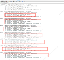
如何 在 TDA4VH EVM 上评估 CPSW-9G 的8个以太网端口? 现在可以使用1个 J721EXENETXPANEVM 评估4个端口。
#1. 我们可以 一起使用两个 J721EXENETXPANEVM 来评估8个端口吗?
从 https://www.ti.com/lit/pdf/spruj74 用户指南中、仅支持一个 QP-ENET 板。
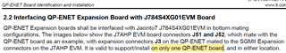
但在后续页面中、已安装两个 QP_ENET。 并具有不同的 EEPROM 地址。

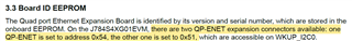
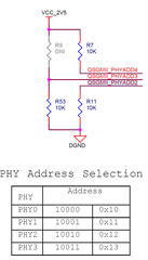
我们是否可以将 PHY 地址更改为两个 ENET 板的差值以同时支持2个?
#2. 我看到另一个 k3-j784s4-evm-usxgmii-exp1-exp2.dtso、应该是为另一个扩展板创建的。 但没有有关这方面的更多信息。