This thread has been locked.

If you have a related question, please click the "Ask a related question" button in the top right corner. The newly created question will be automatically linked to this question.

[参考译文] AM625:SPI0错误检测。

Guru**** 2481905 points
Other Parts Discussed in Thread: AM625

请注意,本文内容源自机器翻译,可能存在语法或其它翻译错误,仅供参考。如需获取准确内容,请参阅链接中的英语原文或自行翻译。

https://e2e.ti.com/support/processors-group/processors/f/processors-forum/1444607/am625-spi0-false-detection

器件型号:AM625

工具与软件:

您好、

我们有基于 AM625的定制电路板。

它在 main_spi0上有两个带有 CS0和 CS1的闪存。

发行 : 我从 CS1卸载闪存 IC 和引导设备,仍然在检测 CS1上的闪存。 显示错误检测。

root@sm2s-am6254:~# cat /proc/mtd
dev:   大小  erasesize 名称
mtd0:10000000 00020000 "spi0.0"
mtd1:00800000 00001000 "spi1.1" <<错误检测   
mtd2:00800000 00001000 "spi1.0"
mtd3:00800000 00001000 "spi2.1" <<错误检测
mtd4:00800000 00001000 "spi2.0"
root@sm2s-am6254:~#


给出的器件树。

&main_pmx0 {
	main_spi0_pins_default: main-spi0-pins-default {
					pinctrl-single,pins = <
							AM62X_IOPAD(0x1bc, PIN_OUTPUT, 0) /* (A14) SPI0_CLK */
							AM62X_IOPAD(0x1c0, PIN_INPUT, 0) /* (B13) SPI0_D0 */
							AM62X_IOPAD(0x1c4, PIN_INPUT, 0) /* (B14) SPI0_D1 */
							AM62X_IOPAD(0x1b4, PIN_OUTPUT, 0) /* (A13) gpio1.15 SPI0_CS0 */
							AM62X_IOPAD(0x1b8, PIN_OUTPUT, 0) /* (C13) gpio1.16 SPI0_CS1 */
					>;
			};
};

&main_spi0 {
        status="okay";
        pinctrl-names = "default";
        pinctrl-0 = <&main_spi0_pins_default>;
        ti,spi-num-cs = <2>;
        ti,pindir-d0-out-d1-in;
		
		flash1@0 {
                                compatible = "winbond,w25q64dw", "jedec,spi-nor";
                                spi-max-frequency = <24000000>;
                                m25p,fast-read;
                                reg = <0x0>;
                        };
						
		flash2@1 {
                                compatible = "winbond,w25q64dw", "jedec,spi-nor";
                                spi-max-frequency = <24000000>;
                                m25p,fast-read;
                                reg = <0x1>;
                        };
};


我们已经探测了 CS0和 CS1的信号、两个引脚一次都变为低电平。 连接下面的信号。


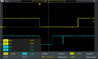
请指导我们什么是问题? 是否涉及芯片选择超时?


谢谢。此致、
Ishan

  • 请注意,本文内容源自机器翻译,可能存在语法或其它翻译错误,仅供参考。如需获取准确内容,请参阅链接中的英语原文或自行翻译。

    尊敬的 Ishan:

    您是否在设备树中定义任何 MTD 分区? 是什么样子的?

    此外、您的内核命令行是什么样的(`cat /proc/cmdline`)? 通常分区通过`mtdparts`以这种方式传递。 此机制会覆盖设备树中的内容(也可以通过 CONFIG_MTD_CMDLINE_PARTS 进行控制)。

    最后、(可能与您此处提出的问题无关)、但 SPI0_CLK 应定义为 PIN_INPUT、TRM 中有一条与此相关的注意事项。

    此致、Andreas

  • 请注意,本文内容源自机器翻译,可能存在语法或其它翻译错误,仅供参考。如需获取准确内容,请参阅链接中的英语原文或自行翻译。

    您好、Andreas、

    感谢您的重播、

    1) 1)未定义设备树中的任何 MTD 分区、设备树节点如下所示

    &main_pmx0 {
    	main_spi0_pins_default: main-spi0-pins-default {
    					pinctrl-single,pins = <
    							AM62X_IOPAD(0x1bc, PIN_INPUT, 0) /* (A14) SPI0_CLK */
    							AM62X_IOPAD(0x1c0, PIN_INPUT, 0) /* (B13) SPI0_D0 */
    							AM62X_IOPAD(0x1c4, PIN_INPUT, 0) /* (B14) SPI0_D1 */
    							AM62X_IOPAD(0x1b4, PIN_OUTPUT, 0) /* (A13) gpio1.15 SPI0_CS0 */
    							AM62X_IOPAD(0x1b8, PIN_OUTPUT, 0) /* (C13) gpio1.16 SPI0_CS1 */
    					>;
    			};
    			
    	main_spi1_pins_default: main-spi1-pins-default {
                    pinctrl-single,pins = <
                            AM62X_IOPAD(0x0020, PIN_INPUT, 1) /* (J25) OSPI0_D5.SPI1_CLK */
                            AM62X_IOPAD(0x001c, PIN_OUTPUT, 1) /* (J23) OSPI0_D4.SPI1_CS0 */
                            AM62X_IOPAD(0x0034, PIN_OUTPUT, 1) /* (H21) OSPI0_CSn2.SPI1_CS1 */
                            AM62X_IOPAD(0x0024, PIN_INPUT, 1) /* (H25) OSPI0_D6.SPI1_D0 */
                            AM62X_IOPAD(0x0028, PIN_INPUT, 1) /* (J22) OSPI0_D7.SPI1_D1 */
                    >;
            };
    };
    
    &main_spi0 {
            status="okay";
            pinctrl-names = "default";
            pinctrl-0 = <&main_spi0_pins_default>;
            ti,spi-num-cs = <2>;
            ti,pindir-d0-out-d1-in;
    		
    		flash1@0 {
                                    compatible = "winbond,w25q64dw", "jedec,spi-nor";
                                    spi-max-frequency = <24000000>;
                                    m25p,fast-read;
                                    reg = <0x0>;
                            };
    						
    		flash2@1 {
                                    compatible = "winbond,w25q64dw", "jedec,spi-nor";
                                    spi-max-frequency = <24000000>;
                                    m25p,fast-read;
                                    reg = <0x1>;
                            };
    };
    
    &main_spi1 {
            status="okay";
            pinctrl-names = "default";
            pinctrl-0 = <&main_spi1_pins_default>;
            ti,spi-num-cs = <2>;
            ti,pindir-d0-out-d1-in;
            
            flash1@0 {
                    compatible = "winbond,w25q64dw", "jedec,spi-nor";
                    spi-max-frequency = <24000000>;
                    m25p,fast-read;
                    reg = <0>;
            };
    
            flash2@1 {
                    compatible = "winbond,w25q64dw", "jedec,spi-nor";
                    spi-max-frequency = <24000000>;
                    m25p,fast-read;
                    reg = <1>;
            };
    };


    2) 2)"/proc/cmdline "如下所示。
    root@sm2s-am6254:~# cat /proc/cmdline             
    console=ttyS2,115200n8 earlycon=ns16550a,mmio32,0x02800000 mtdparts=spi-nand0:512k(ospi.tiboot3),2m(ospi.tispl),4m(ospi.u-boot),256k(ospi.env),256k(ospi.env.backup),98048k@32m(ospi.rootfs),256k@130816k(ospi.phyp
    attern);omap2-nand.0:2m(NAND.tiboot3),2m(NAND.tispl),2m(NAND.tiboot3.backup),4m(NAND.u-boot),256k(NAND.u-boot-env),256k(NAND.u-boot-env.backup),-(NAND.file-system) root=PARTUUID=cc8878cf-02 rw rootfstype=ext4 ro
    otwait


    还从 u-boot 进行检查
    => print mtdparts 
    mtdparts=mtdparts=spi-nand0:512k(ospi.tiboot3),2m(ospi.tispl),4m(ospi.u-boot),256k(ospi.env),256k(ospi.env.backup),98048k@32m(ospi.rootfs),256k@130816k(ospi.phypattern);omap2-nand.0:2m(NAND.tiboot3),2m(NAND.tisp
    l),2m(NAND.tiboot3.backup),4m(NAND.u-boot),256k(NAND.u-boot-env),256k(NAND.u-boot-env.backup),-(NAND.file-system)


    3)内核配置" CONFIG_MTD_CMDLINE_PARTS "也已启用  


    正如您提到的 、它可以覆盖设备树、我更改了 mtdparts 自 u-boot。 仍然会得到错误的 SPI 闪存检测。 下面提供了详细的日志。
    U-Boot 2023.04 (Oct 29 2024 - 10:45:21 +0000)
    
    SoC:   AM62X SR1.0 HS-FS
    Model: Avnet sm2s-am6254 smarc module
    DRAM:  2 GiB
    Core:  82 devices, 31 uclasses, devicetree: separate
    MMC:   mmc@fa10000: 0, mmc@fa00000: 1
    Loading Environment from MMC... OK
    In:    serial@2800000
    Out:   serial@2800000
    Err:   serial@2800000
    Net:   eth0: ethernet@8000000port@1
    Hit any key to stop autoboot:  0 
    => 
    => 
    => print mtdparts
    ## Error: "mtdparts" not defined
    => 
    
    
    root@sm2s-am6254:~# 
    root@sm2s-am6254:~# 
    root@sm2s-am6254:~# cat /proc/cmdline 
    console=ttyS2,115200n8 earlycon=ns16550a,mmio32,0x02800000 root=PARTUUID=cc8878cf-02 rw rootfstype=ext4 rootwait
    root@sm2s-am6254:~# 
    
    root@sm2s-am6254:~# cat /proc/mtd    
    dev:    size   erasesize  name
    mtd0: 10000000 00020000 "spi0.0"        <<            QSPI
    mtd1: 00800000 00001000 "spi1.1"        <<          false detection
    mtd2: 00800000 00001000 "spi1.0"        <<
    mtd3: 00800000 00001000 "spi2.1"        <<          false detection
    mtd4: 00800000 00001000 "spi2.0"
    root@sm2s-am6254:~# 


    请指导我们进行相同的操作、出于调试目的、我还保存了逻辑分析仪的数字信号、但无法在此处附上(上传)。  

    只需连接初始信号序列的屏幕截图  

    两个观察结果均针对 SPI0得出。


    谢谢。此致
    Ishan

  • 请注意,本文内容源自机器翻译,可能存在语法或其它翻译错误,仅供参考。如需获取准确内容,请参阅链接中的英语原文或自行翻译。

    尊敬的 Ishan:

    我只是注意到该线程仍然是打开的。 您是否能够确定问题是什么?

    此致、Andreas