This thread has been locked.

If you have a related question, please click the "Ask a related question" button in the top right corner. The newly created question will be automatically linked to this question.

[参考译文] IWR6843AOP:改进 3D 跟踪人员示例中的最大距离检测(壁挂式安装)

Guru**** 2415460 points


请注意,本文内容源自机器翻译,可能存在语法或其它翻译错误,仅供参考。如需获取准确内容,请参阅链接中的英语原文或自行翻译。

https://e2e.ti.com/support/sensors-group/sensors/f/sensors-forum/1526813/iwr6843aop-improve-max-range-detection-in-3d-tracking-people-example-wall-mount

器件型号:IWR6843AOP

工具/软件:

我想恢复这一主题、因为我已恢复该项目的工作。

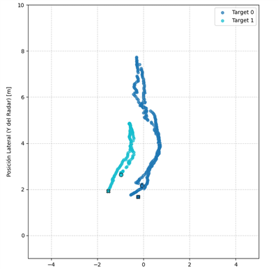
通过当前配置、我能够准确地检测到周围的物体 12 米 。 超过该距离后、便会失去检测功能。 我尝试过调整 较低的开关频率 、但我没有观察到检测范围有任何明显的改善。


引用到我的最后一个帖子相关:

Hi everyone,

I've been working with the IWR6843AOP sensor using the 3D People Tracking demo, with the sensor mounted on a wall at a 15° downward tilt. I've run several tests, adjusting the detection and tracking parameters across different configurations. I'm using the IWR6843AOP EVM board and configuring its parameters based on the documentation in Section 4 of the 3D People Tracking Demo Detection Layer Tuning Guide.

However, in nearly all cases, the maximum detection range caps at around 12.5 meters. Beyond this distance, no point cloud is detected, and no target is tracked.

In my most recent test, I increased the transmission power by configuring the txOutPowerBackoff to 0 dB, which did result in extended detection up to 14 meters in some cases—but with significantly more background noise throughout the reading.

I’d like to understand whether:

    There’s something potentially misconfigured in my setup that's causing this limitation, or
    The sensor is inherently limited to around 12.5 meters in most real-world scenarios, despite parameter tuning.

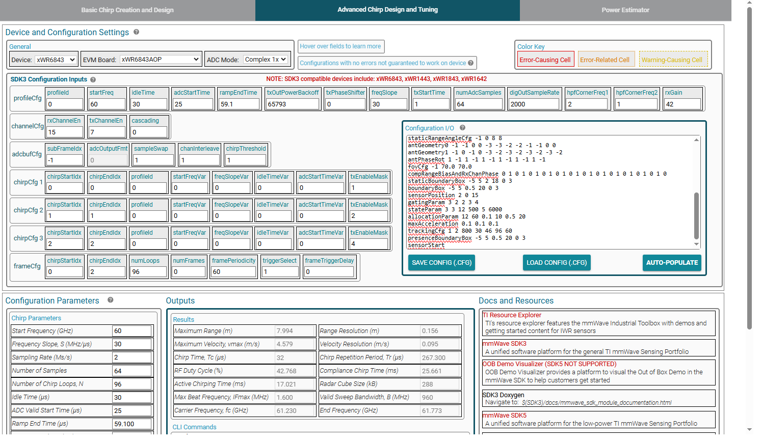
Any insights or suggestions would be greatly appreciated!


此外、任何人都能告诉我使用了什么软件来根据获取传感器指标吗 .cfg 文件 显示的内容吗? 这个工具看起来非常有用。

  • 请注意,本文内容源自机器翻译,可能存在语法或其它翻译错误,仅供参考。如需获取准确内容,请参阅链接中的英语原文或自行翻译。

    您好、

    请发布您的整个 cfg 文件。 问题是你看到绝对没有检测超过 12 米吗? 或者检测速率似乎下降到 12 米以上?

    此致、

    Nate

  • 请注意,本文内容源自机器翻译,可能存在语法或其它翻译错误,仅供参考。如需获取准确内容,请参阅链接中的英语原文或自行翻译。

    这是我的 cfg、  

    sensorStop
    flushCfg
    dfeDataOutputMode 1
    channelCfg 15 7 0
    adcCfg 2 1
    adcbufCfg -1 0 1 1 1
    lowPower 0 0
    profileCfg 0 60.00 30.00 25.00 59.10 65793 0 30 1 64 2000.00 2 1 42 
    chirpCfg 0 0 0 0 0 0 0 1
    chirpCfg 1 1 0 0 0 0 0 2
    chirpCfg 2 2 0 0 0 0 0 4
    frameCfg 0 2 96 0 60.00 1 0
    dynamicRACfarCfg -1 4 4 2 2 8 12 4 12 10 8.00 0.40 1 3
    staticRACfarCfg -1 6 2 2 2 8 8 6 4 8.00 15.00 0.30 0 0
    dynamicRangeAngleCfg -1 0.75 0.0010 1 0
    dynamic2DAngleCfg -1 3.0 0.0300 1 0 1 0.30 0.85 8.00
    staticRangeAngleCfg -1 0 8 8
    antGeometry0 -1 -1 0 0 -3 -3 -2 -2 -1 -1 0 0
    antGeometry1 -1 0 -1 0 -3 -2 -3 -2 -3 -2 -3 -2
    antPhaseRot 1 -1 1 -1 1 -1 1 -1 1 -1 1 -1
    fovCfg -1 70.0 70.0
    compRangeBiasAndRxChanPhase 0 1 0 1 0 1 0 1 0 1 0 1 0 1 0 1 0 1 0 1 0 1 0 1 0
    staticBoundaryBox -5 5 2 18 0 3
    boundaryBox -5 5 0.5 20 0 3
    sensorPosition 2 0 15
    gatingParam 3 2 2 3 4
    stateParam 3 3 12 500 5 6000
    allocationParam 12 60 0.1 10 0.5 20
    maxAcceleration 0.1 0.1 0.1
    trackingCfg 1 2 800 30 46 96 60
    presenceBoundaryBox -5 5 0.5 20 0 3
    sensorStart


    超过 12 米后我看不到任何检测、没有点云、没有目标。

    我想使用图像中显示的软件尝试达到应用所需的指标、但我不知道它是什么。 在哪里可以找到它?

  • 请注意,本文内容源自机器翻译,可能存在语法或其它翻译错误,仅供参考。如需获取准确内容,请参阅链接中的英语原文或自行翻译。

    您好、

    https://dev.ti.com/gallery/view/mmwave/mmWaveSensingEstimator/ver/2.5.0/

    您可以通过这种方式在图像中查看视图。

    您需要更改频率斜率 — 现在设置为仅在 8m 时检测。 我知道您曾尝试过、但您上面发布的配置仅适用于 8m。

    修改频率斜率时、您看不到检测范围变化吗?

    此致、

    Nate

  • 请注意,本文内容源自机器翻译,可能存在语法或其它翻译错误,仅供参考。如需获取准确内容,请参阅链接中的英语原文或自行翻译。

    尊敬的 Nate:  

    我已使用该软件为我的应用找到合适的斜率值、但我有一些疑问和结果需要讨论。

    首先、斜率值是任意值、还是与其他参数相关?

    我使用了能提供所需范围的斜率值进行测试、但现在遇到了一个问题、即为一个人生成了两条轨迹。 对于轨迹的很大一部分、会将两个跟踪 ID 分配给该区域中的同一个人。 由于这似乎是由修改斜率频率引起的、您能否提供有关如何缓解此问题的建议?

    我们进行了一个测试、一个人向前走了大概 8 米、然后沿着同一条路径返回。 结果如下图所示。

    蓝色点表示人的正确轨迹。

    浅蓝色点对应于幻影轨迹或反射、它略微出现在真实路径的左侧。

    值得注意的是、该区域只有一张桌子、附近没有任何墙可以解释强烈的反射。

    我们已经尝试调整以下参数:

    SnrThre

    snrThreObsgraded

    点主题

    我们还尝试按每帧的置信水平进行筛选、但反射轨迹始终报告置信水平高于 0.80、因此很难仅根据该指标来丢弃。

    sensorStop
    flushCfg
    dfeDataOutputMode 1
    channelCfg 15 7 0
    adcCfg 2 1
    adcbufCfg -1 0 1 1 1
    lowPower 0 0
    profileCfg 0 60.75 30.00 25.00 59.10 65793 0 24.4 1 96 2950.00 2 1 40
    chirpCfg 0 0 0 0 0 0 0 1
    chirpCfg 1 1 0 0 0 0 0 2
    chirpCfg 2 2 0 0 0 0 0 4
    frameCfg 0 2 96 0 60.00 1 0
    dynamicRACfarCfg -1 4 4 2 2 8 12 4 12 10 8.00 0.40 1 3
    staticRACfarCfg -1 6 2 2 2 8 8 6 4 8.00 15.00 0.30 0 0
    dynamicRangeAngleCfg -1 0.75 0.0010 1 0
    dynamic2DAngleCfg -1 3.0 0.0300 1 0 1 0.30 0.85 8.00
    staticRangeAngleCfg -1 0 8 8
    antGeometry0 -1 -1 0 0 -3 -3 -2 -2 -1 -1 0 0
    antGeometry1 -1 0 -1 0 -3 -2 -3 -2 -3 -2 -3 -2
    antPhaseRot 1 -1 1 -1 1 -1 1 -1 1 -1 1 -1
    fovCfg -1 70.0 70.0
    compRangeBiasAndRxChanPhase 0 1 0 1 0 1 0 1 0 1 0 1 0 1 0 1 0 1 0 1 0 1 0 1 0
    staticBoundaryBox -1 2 0.5 16 -5 5
    boundaryBox -1 2 0.5 16 -5 5
    sensorPosition 0 15 0
    gatingParam 4 2 2 2 4
    stateParam 2 3 12 200 2 600
    allocationParam 35 160 0.1 20 0.5 25
    maxAcceleration 0.2 0.2 0.2
    trackingCfg 1 2 800 30 46 96 60
    presenceBoundaryBox -1 2 0.5 16 -5 5
    sensorStart


    e2e.ti.com/.../6661.target_5F00_0.csv
    e2e.ti.com/.../6661.target_5F00_1.csv

  • 请注意,本文内容源自机器翻译,可能存在语法或其它翻译错误,仅供参考。如需获取准确内容,请参阅链接中的英语原文或自行翻译。

    您好、

    我推荐您参考此处的此文档。

    https://dev.ti.com/tirex/explore/node?a=1AslXXD__3.10.00.05&node=A__AZpgHWE6lzA-KRs9lGPdhw__radar_toolbox__1AslXXD__3.10.00.05&r=1AslXXD__1.00.00.26&r=1AslXXD__1.00.01.07&r=1AslXXD__1.30.00.05

    请参阅第 4.2 节

    此致、

    Nate