

尊敬的 TI 支持团队:
我目前正在测试 远距离人员检测 工程的可行解决方案 IWR6843ISK 视图。
将以下 CFG 文件导入到中时 “mmWave Industrial Visualizer.exe“ 、则主板成功传输 点云数据 到 GUI。
sensorStop
flushCfg
dfeDataOutputMode 1
channelCfg 15 7 0
adcCfg 2 1
adcbufCfg –1 0 1 1
profileCfg 0 60 35 6 43.0 0 0 8.241 1 125 3433 0 48
chirpCfg 0 0 0 0 0 0 0 1
chirpCfg 1 1 1 0 0 0 0 4
chirpCfg 2 2 0 0 0 0 2
frameCfg 0 2 96 0 100 1 0
低功率 0 0
guiMonitor –1 1 0 0 0 0 0
cfarCfg –1 0 2 8 4 0 10 0
cfarCfg –1 1 0 4 2 3 1 10 0
MultiObjBeamForming –1 1 0.5
离合器拆卸–1 1.
calibDcRangeSig –1 0 –5 8 256
extendedMaxVelocity –1 0
bpmCfg –1 0 0 1
lvdsStreamCfg –1 0 0
compRangeBiasAndRxChanPhase 0.0 1 0 1 0 1 0 1 0 1 0 1 0 1 0 1 0 1 0 1 0 1 0 1 0 1 0
MeasureRangeBiasAndRxChanPhase 0 1.5 0.2
CQRxSatMonitor 0 3 4 63 0
CQSigImgMonitor 0 127 4.
模拟监视器 0 0
aoFovCfg –1 –90 90 –90 90
cfarFovCfg –1 0 0 59.99
CFarFovCfg –1 –30 30.00
StaticBoundaryBox –50 0.5 60 –0.5 6.
boundaryBox –50 0.5 60 –0.5 6.
sensorPosition 2 0
gatingParam 4 6 6 6 10
StateParam 4 10 60 600 20 600
分配参数 30 0.5 3 2 2.
最大加速度 0.1 0.1 0.1
第 99 章我的朋友
PreenceBoundaryBox –3 2 6 0.5 2.5
sensorStart
但是、当我导入时 修改了 CFG 文件 如下所示、GUI 不会从电路板接收任何点云数据。
sensorStop
flushCfg
dfeDataOutputMode 1
channelCfg 15 7 0
adcCfg 2 1
adcbufCfg –1 0 1 1
profileCfg 0 60 8 7 28 0 0 20 1 256 12500 0 30
chirpCfg 0 0 0 0 0 0 0 1
chirpCfg 1 1 1 0 0 0 0 4
chirpCfg 2 2 0 0 0 0 2
frameCfg 0 2 64 0 100 1 0
低功率 0 0
guiMonitor –1 1 0 0 0 0 0
cfarCfg –1 0 2 8 4 0 10 0
cfarCfg –1 1 0 4 2 3 1 10 0
MultiObjBeamForming –1 1 0.5
离合器拆卸–1 1.
calibDcRangeSig –1 0 –5 8 256
extendedMaxVelocity –1 0
bpmCfg –1 0 0 1
lvdsStreamCfg –1 0 0
compRangeBiasAndRxChanPhase 0.0 1 0 1 0 1 0 1 0 1 0 1 0 1 0 1 0 1 0 1 0 1 0 1 0 1 0
MeasureRangeBiasAndRxChanPhase 0 1.5 0.2
CQRxSatMonitor 0 3 4 63 0
CQSigImgMonitor 0 127 4.
模拟监视器 0 0
aoFovCfg –1 –90 90 –90 90
cfarFovCfg –1 0 0 59.99
CFarFovCfg –1 –30 30.00
StaticBoundaryBox –50 0.5 60 –0.5 6.
boundaryBox –50 0.5 60 –0.5 6.
sensorPosition 2 0
gatingParam 4 6 6 6 10
StateParam 4 10 60 600 20 600
分配参数 30 0.5 3 2 2.
最大加速度 0.1 0.1 0.1
第 99 章我的朋友
PreenceBoundaryBox –3 2 6 0.5 2.5
sensorStart
我所做的唯一更改在下图中突出显示。
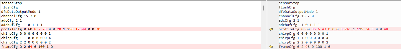
您能回顾一下为什么此配置不能正常工作、
其他参数保持相同的结构、这也是怎样的呢?
感谢您的帮助。
此致、
金在勋

