请注意,本文内容源自机器翻译,可能存在语法或其它翻译错误,仅供参考。如需获取准确内容,请参阅链接中的英语原文或自行翻译。
器件型号:AWR6843AOPEVM 主题中讨论的其他器件: AWR6843AOP
您好!
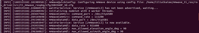
因此、我需要通过 AWR6843AOPEVM 电路板为我的项目使用 ROS、我稍微深入文档、主要是 TI 毫米波 ROS 驱动程序用户指南。
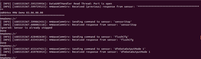
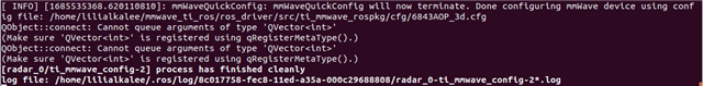
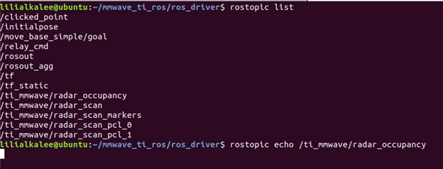
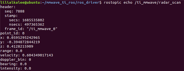
我将演示刷入了雷达、完成了与驱动程序和所有组件的每一步。 一旦我开始启动6843AOP_MULTI_2D_0.LAUNCH 文件(用于测试)、我没有收到错误。 但是、当我查看我的主题时、终端中没有收到任何内容。 为什么会这样。
在本例中是否有其他 ROS 引线需要研究。
谢谢。此致。