

请注意,本文内容源自机器翻译,可能存在语法或其它翻译错误,仅供参考。如需获取准确内容,请参阅链接中的英语原文或自行翻译。
器件型号:TIDA-00663 主题中讨论的其他器件:MSP430FR5969、 OPA857
您好!
在 TIDA-00663 参考设计中、我一直使用从 MSP430FR5969 到 TDC7200的16MHz 外部时钟源。
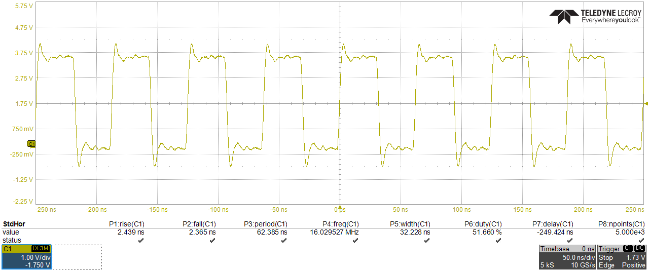
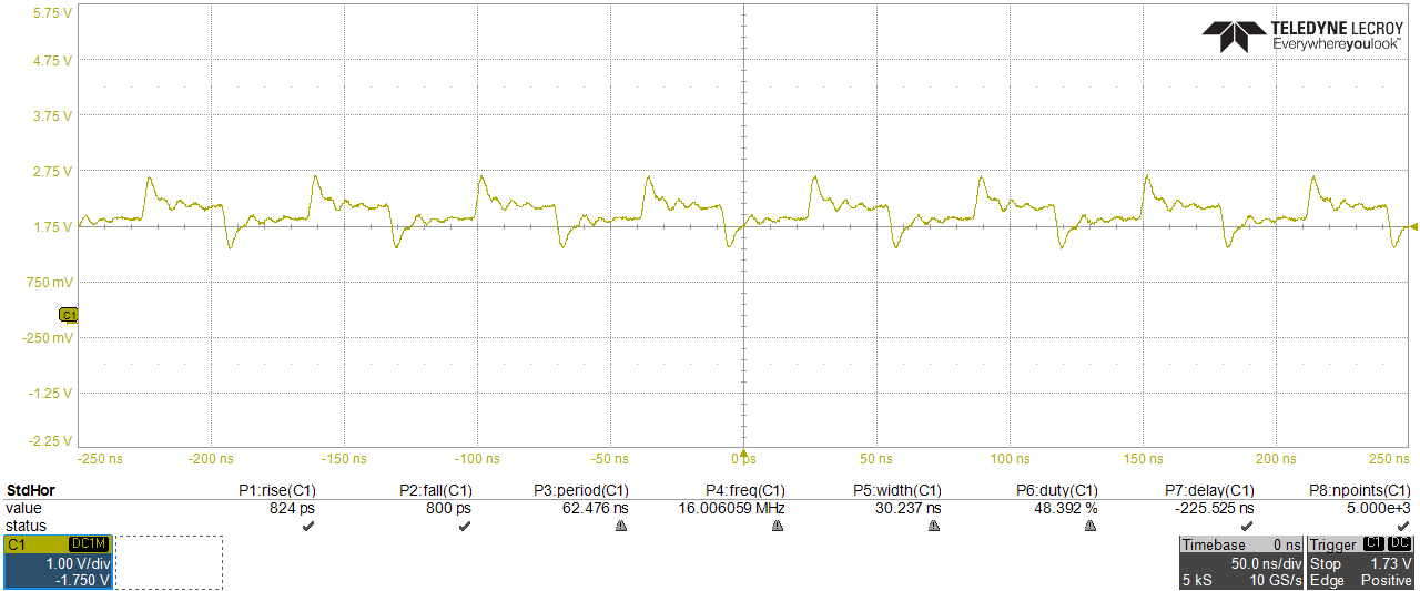
但是、我刚刚注意 到、在 OPA857 输出端、有一个频率相同的16MHz 振荡。
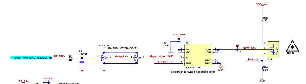
除了激光驱动器(U2)和激光(U10)外、PCB 上焊接的每个组件都是相应的电阻器和电容器

我用于设置 OPA857 和 TDC_CLK 的代码如下:
#include <msp430fr5969.h> #include <SPI.h> #define nop __asm__ __volatile__("nop\n\t"); // no operation instruction that wastes 1 CLK cycle (1/16MHz=62.5ns) voidsetup() { // Setup the system // WDTCTL = WDTPW | WDTHOLD; // Stop the Watchdog Timer => AFFECTS Serial communication PM5CTL0 &= ~LOCKLPM5; // Disable the GPIO power-on default impedance mode to activate previously configured port settings // Output SMCLK in P3.4 (dedicated pin) with the same frequency as F_CPU=16MHz (maximum for TDCs) - TDC_CLK P3DIR |= 0x10; // Set P3.4 as an output P3SEL1 |= 0x10; // Select SMCLK function (Table 6-57 from MSP430FR5969 datasheet) //Set the OPA P3DIR |= 0b01100000; // Set OPA857 (TIA) gain in CTRL pin P3.5 (5k_gain_setting_BP9_P3.5) and Test_mode in P3.6 P3OUT &= ~0x20; // If TIA_gain = 5 => P3.5 = '0', if TIA_gain = 20 => P3.5 = '1' P3OUT &=~ 0x40; // Disable test mode in P3.6 (tprop_calibration_enable_BP10_P3.6 <=> Test_SD writen to '0') } voidloop(){ // Code to run repeatedly nop; // Nothing happens here, when TDC finishes, an interrupt is activated nop; } |
因此、我将以下信号分别作为时钟和 OPA 输出。 应该注意的是、如果我将 OPA 增益增加到20kOhm、输出振荡自然也会被放大。
如果有人能帮助找到消息来源、我会很感激。
提前感谢、
Joaquim
