This thread has been locked.

If you have a related question, please click the "Ask a related question" button in the top right corner. The newly created question will be automatically linked to this question.

[参考译文] LAUNCHXL-CC1312R1:如何动态切换 UART 引脚功能

Guru**** 2481895 points


请注意,本文内容源自机器翻译,可能存在语法或其它翻译错误,仅供参考。如需获取准确内容,请参阅链接中的英语原文或自行翻译。

https://e2e.ti.com/support/tools/simulation-hardware-system-design-tools-group/sim-hw-system-design/f/simulation-hardware-system-design-tools-forum/1459567/launchxl-cc1312r1-how-to-dynamically-switch-uart-pin-functions

器件型号:LAUNCHXL-CC1312R1

工具与软件:

您好!

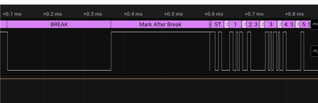
我希望动态切换 UART TX 引脚以模拟 DMX 帧。 具体来说、我需要 Tx 引脚首先作为一个可以上拉/下拉引脚电平来模拟中断/MAB 的 GPIO、然后作为一个 UART TX 引脚来传输512槽数据。

我看到有人在做与我相同的事情:
https://e2e.ti.com/support/microcontrollers/msp-low-power-microcontrollers-group/msp430/f/msp-low-power-microcontroller-forum/992945/msp432e401y-change-uart-idle-state/3670821?tisearch=e2e-sitesearch&keymatch=DMX#3670821

似乎效果也不好。

下面是我的函数:

static void DMX_TX(uint8_t *data, uint16_t len)
{
    UART2_close(uart);
    //IO function change
    GPIO_setConfig(3, GPIO_CFG_OUT_STD | GPIO_CFG_OUT_LOW);
    //BREAK Frame
	GPIO_write(3, CONFIG_GPIO_LED_OFF);
	usleep(88);
    //MAB Frame
	GPIO_write(3, CONFIG_GPIO_LED_ON);
	usleep(8);

   //IO function chang
   /* Access UART */
   uart = UART2_open(CONFIG_UART2_0, &uartParams);

    UART2_write(uart, data, len, NULL);
}

由于上电时我已经将 DIO3初始化为 UART TX 引脚、因此我应该先在函数中禁用 UART、但我没有找到任何禁用或取消初始化函数。 我使用了关闭功能、 但到目前为止、TX 引脚已保持高电平、这似乎没有效果。

我想确认这种切换是否可行、如果可行、我该如何做呢?

  • 请注意,本文内容源自机器翻译,可能存在语法或其它翻译错误,仅供参考。如需获取准确内容,请参阅链接中的英语原文或自行翻译。

    您不必打开和关闭驱动程序(我认为)。 我从 SDK 中获取了 uartExco 示例、并添加了以下命令来在每次迭代中切换 TX 引脚几次、这样做是有效的:

        while (1)
        {
            bytesRead = 0;
            while (bytesRead == 0)
            {
                status = UART2_read(uart, &input, 1, &bytesRead);
    
                if (status != UART2_STATUS_SUCCESS)
                {
                    /* UART2_read() failed */
                    while (1) {}
                }
            }
    
            bytesWritten = 0;
            while (bytesWritten == 0)
            {
                status = UART2_write(uart, &input, 1, &bytesWritten);
    
                if (status != UART2_STATUS_SUCCESS)
                {
                    /* UART2_write() failed */
                    while (1) {}
                }
            }
    
            GPIO_setConfigAndMux(CONFIG_GPIO_UART2_0_TX, GPIO_CFG_OUT_STD, IOC_PORT_GPIO);
    
            GPIO_write(CONFIG_GPIO_UART2_0_TX, 0);
            GPIO_write(CONFIG_GPIO_UART2_0_TX, 1);
            GPIO_write(CONFIG_GPIO_UART2_0_TX, 0);
            GPIO_write(CONFIG_GPIO_UART2_0_TX, 1);
            
            GPIO_setConfigAndMux(CONFIG_GPIO_UART2_0_TX, GPIO_CFG_OUT_STD, IOC_PORT_MCU_UART0_TX);
        }

    Siri

  • 请注意,本文内容源自机器翻译,可能存在语法或其它翻译错误,仅供参考。如需获取准确内容,请参阅链接中的英语原文或自行翻译。

    你好、Siri、

    感谢您的帮助、GPIO_setConfigAndMux 对于开关引脚很有效。  我还有一个有关 us 延迟函数的问题:

    我发现 usleep()函数不准确,阅读了论坛上的其他问题后,我使用了推荐的 ClockP_usleep()函数,它似乎也不准确,是否有任何其他解决方案

    我设置10微秒的延迟:

    static void DMX_TX(uint8_t *data, uint16_t len)
    {
        GPIO_setConfigAndMux(CONFIG_PIN_UART_TX, GPIO_CFG_OUT_STD, IOC_PORT_GPIO);
    
        //IO function change
        GPIO_setConfig(CONFIG_PIN_UART_TX, GPIO_CFG_OUT_STD | GPIO_CFG_OUT_LOW);
        //BREAK Frame
    	GPIO_write(CONFIG_PIN_UART_TX, CONFIG_GPIO_LED_OFF);
    	ClockP_usleep(10);
        //MAB Frame
    	GPIO_write(CONFIG_PIN_UART_TX, CONFIG_GPIO_LED_ON);
    	ClockP_usleep(10);
    
    	GPIO_setConfigAndMux(CONFIG_PIN_UART_TX, GPIO_CFG_OUT_STD, IOC_PORT_MCU_UART0_TX);
       //IO function chang
       /* Access UART */
        UART2_write(uart, data, len, NULL);
    }

    实际捕获结果:

    如这个链接 https://e2e.ti.com/support/wireless-connectivity/bluetooth-group/bluetooth/f/bluetooth-forum/1389192/cc2340r5-short-pause-with-usleep-function-1millisecond/5312278?tisearch=e2e-sitesearch&keymatch=ClockP_usleep#5312278中所述、只有当延迟超过1ms 时、似乎才会发生变化

  • 请注意,本文内容源自机器翻译,可能存在语法或其它翻译错误,仅供参考。如需获取准确内容,请参阅链接中的英语原文或自行翻译。

    你见过以下章节吗?

    (+) CC1352R:TIRTOS 用户睡眠精度-低于1GHz 论坛-低于1GHz - TI E2E 支持论坛

    您可以尝试使用 CPUdelay 函数:

    //*****************************************************************************
    //
    //! \brief Provide a small non-zero delay using a simple loop counter.
    //!
    //! This function provides means for generating a constant length delay. It
    //! is written in assembly to keep the delay consistent across tool chains,
    //! avoiding the need to tune the delay based on the tool chain in use.
    //!
    //! \note It is not recommended using this function for long delays.
    //!
    //! Notice that interrupts can affect the delay if not manually disabled in advance.
    //!
    //! The delay depends on where code resides and the path for code fetching:
    //! - Code in flash, cache enabled, prefetch enabled  : 4 cycles per loop (Default)
    //! - Code in flash, cache enabled, prefetch disabled : 5 cycles per loop
    //! - Code in flash, cache disabled                   : 7 cycles per loop
    //! - Code in SRAM                                    : 6 cycles per loop
    //! - Code in GPRAM                                   : 3 cycles per loop
    //!
    //! \note If using an RTOS, consider using RTOS provided delay functions because
    //! these will not block task scheduling and will potentially save power.
    //!
    //! Calculate delay count based on the wanted delay in microseconds (us):
    //! - ui32Count = [delay in us] * [CPU clock in MHz] / [cycles per loop]
    //!
    //! Example: 250 us delay with code in flash and with cache and prefetch enabled:
    //! - ui32Count = 250 * 48 / 4 = 3000
    //!
    //! \param ui32Count is the number of delay loop iterations to perform. Number must be greater than zero.
    //!
    //! \return None
    //
    //*****************************************************************************
    extern void CPUdelay(uint32_t ui32Count);

    另请注意 GPIO_write 函数的执行时间有限、因此您需要进行补偿。

    BR

    Siri

  • 请注意,本文内容源自机器翻译,可能存在语法或其它翻译错误,仅供参考。如需获取准确内容,请参阅链接中的英语原文或自行翻译。

    感谢您的回答、此函数运行良好