This thread has been locked.

If you have a related question, please click the "Ask a related question" button in the top right corner. The newly created question will be automatically linked to this question.

[参考译文] CC1312R7:PWM 计时器间隔匹配重载异常行为

Guru**** 2577385 points
Other Parts Discussed in Thread: CC1312R7, CC1312R

请注意,本文内容源自机器翻译,可能存在语法或其它翻译错误,仅供参考。如需获取准确内容,请参阅链接中的英语原文或自行翻译。

https://e2e.ti.com/support/wireless-connectivity/sub-1-ghz-group/sub-1-ghz/f/sub-1-ghz-forum/1572687/cc1312r7-pwm-timer-interval-match-reload-strange-behaviour

器件型号:CC1312R7
主题中讨论的其他器件: CC1312R

工具/软件:

您好、

对于基于 CC1312R7 的工程 ( simplelink_cc13xx_cc26xx_sdk_6_30_01_03)、TI_RTOS7 我需要通过重复模式实现声音生成(以驱动 Siren)、家长由 2.8kHz 至 2kHz 范围内的 20 个频率组成、因为声音从 2.8kHz 开始、每 5ms 降至 2kHz、然后再次从 2.8kHz 开始。 所有频率的占空比值必须相同、这意味着要更改频率周期/加载值和匹配值、则必须更改此值。   

若要实现此声音生成、我使用 SDK 中的 PWM 驱动程序进行两处修改:  

1.在 pwm_open() 之后、我设置了 TxMRA.TxILD 位(换言之,将 mode 设置为 GPT_Tamr_TAILD_toupdate) 、以便只在计时器超时更新间隔。

2.将 PWM_PERIOD_for_glitch_protection 值从 16 增加到 960(约为 20us)。

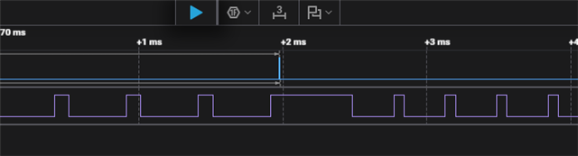
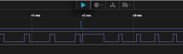
问题是、几乎每次在 2kHz 至 2.8kHz 频率范围内设置新的间隔和匹配值时、PWM 输出都会出现问题、如下图所示(第一个信号显示了调用 Set load 和 match value 函数时的情况、第二个信号是 PWM 输出)。 此外、还添加了逻辑分析仪中的完整文件、以获取更多信息(可通过 Saleae 应用程序打开)。  

e2e.ti.com/.../Siren_5F00_PWM_5F00_Perior_5F00_load_5F00_Issue2_5F00_Out_2600_Period_5F00_Match_5F00_Load.zip

问题是否存在有关 PWM/GPTimer 加载和匹配值设置/重新加载的任何已知问题、如果不是、什么原因会导致此行为?  

也欢迎任何关于如何解决这一问题的想法。

此致。

Dimitar

  • 请注意,本文内容源自机器翻译,可能存在语法或其它翻译错误,仅供参考。如需获取准确内容,请参阅链接中的英语原文或自行翻译。

    尊敬的 Dimitar:

    自从您使用的 SDK 版本以来、我看不到任何有关 PWM 的已知或修复问题。

    如果您也在使用 AES、我们有一个 GPTimer 勘误表。  https://www.ti.com/lit/swrz078 

    谢谢、

    Marie H

  • 请注意,本文内容源自机器翻译,可能存在语法或其它翻译错误,仅供参考。如需获取准确内容,请参阅链接中的英语原文或自行翻译。

    尊敬的 Marie:

    您给我的链接是 CC1312R、我的工程是 CC1312R7。 CC1312R7 的勘误表未列出 GPTimer 的问题。 实际上、CC1312R 勘误表中提到的这个 GPTimer 问题是否也被视为对 CC1312R7 有效、如果是、勘误表说明中的主器件含义是什么?

    此致、

    Dimitar

  • 请注意,本文内容源自机器翻译,可能存在语法或其它翻译错误,仅供参考。如需获取准确内容,请参阅链接中的英语原文或自行翻译。

    尊敬的 Dimitar:

    我将根据您的当前方法查找问题、但我也可以建议其他解决方案。 下述命令使用该计时器、与 DMA 配合使用:

    /*
     * Copyright (c) 2015-2019, Texas Instruments Incorporated
     * All rights reserved.
     *
     * Redistribution and use in source and binary forms, with or without
     * modification, are permitted provided that the following conditions
     * are met:
     *
     * *  Redistributions of source code must retain the above copyright
     *    notice, this list of conditions and the following disclaimer.
     *
     * *  Redistributions in binary form must reproduce the above copyright
     *    notice, this list of conditions and the following disclaimer in the
     *    documentation and/or other materials provided with the distribution.
     *
     * *  Neither the name of Texas Instruments Incorporated nor the names of
     *    its contributors may be used to endorse or promote products derived
     *    from this software without specific prior written permission.
     *
     * THIS SOFTWARE IS PROVIDED BY THE COPYRIGHT HOLDERS AND CONTRIBUTORS "AS IS"
     * AND ANY EXPRESS OR IMPLIED WARRANTIES, INCLUDING, BUT NOT LIMITED TO,
     * THE IMPLIED WARRANTIES OF MERCHANTABILITY AND FITNESS FOR A PARTICULAR
     * PURPOSE ARE DISCLAIMED. IN NO EVENT SHALL THE COPYRIGHT OWNER OR
     * CONTRIBUTORS BE LIABLE FOR ANY DIRECT, INDIRECT, INCIDENTAL, SPECIAL,
     * EXEMPLARY, OR CONSEQUENTIAL DAMAGES (INCLUDING, BUT NOT LIMITED TO,
     * PROCUREMENT OF SUBSTITUTE GOODS OR SERVICES; LOSS OF USE, DATA, OR PROFITS;
     * OR BUSINESS INTERRUPTION) HOWEVER CAUSED AND ON ANY THEORY OF LIABILITY,
     * WHETHER IN CONTRACT, STRICT LIABILITY, OR TORT (INCLUDING NEGLIGENCE OR
     * OTHERWISE) ARISING IN ANY WAY OUT OF THE USE OF THIS SOFTWARE,
     * EVEN IF ADVISED OF THE POSSIBILITY OF SUCH DAMAGE.
     */
    
    /*
     *  ======== empty.c ========
     */
    
    /* For usleep() */
    #include <unistd.h>
    #include <stdint.h>
    #include <stddef.h>
    
    /* Driver Header files */
    #include <ti/drivers/GPIO.h>
    #include <ti/drivers/PWM.h>
    #include <ti/drivers/timer/GPTimerCC26XX.h>
    #include <ti/drivers/dma/UDMACC26XX.h>
    // #include <ti/drivers/I2C.h>
    // #include <ti/drivers/SPI.h>
    // #include <ti/drivers/Watchdog.h>
    
    /* Driver configuration */
    #include "ti_drivers_config.h"
    
    #define CONFIG_GPIO_PWM_0 6
    
    ALLOCATE_CONTROL_TABLE_ENTRY(dmaGPT0APriControlTableEntry, UDMA_CHAN_TIMER0_A);
    
    UDMACC26XX_Handle dmaHandle;
    
    //assume duty cycle period = 100 (count)
    uint16_t myPwmDutyInCounts[6] = {
    
        80,    /* 20% duty */
        70,    /* 30% duty */
        60,   /* 40% duty */
        50,   /* 50% duty */
        40,   /* 60% duty */
        100,   /* stop */
    };
    
    /*
     *  ======== mainThread ========
     */
    void *mainThread(void *arg0)
    {
        /* 1 second delay */
        uint32_t time = 1;
    
        /* Call driver init functions */
        GPIO_init();
        PWM_init();
        dmaHandle = UDMACC26XX_open();
    
    
        /* Configure the PWM pin */
        GPIO_setConfig(CONFIG_GPIO_PWM_0, GPIO_CFG_OUTPUT_INTERNAL | GPIO_CFG_OUT_STR_MED | GPIO_CFG_OUT_LOW);
    
        /* Initialize the PWM parameters */
        PWM_Params pwmParams;
        PWM_Params_init(&pwmParams);
        pwmParams.idleLevel = PWM_IDLE_LOW;         /* Output low when PWM is not running */
        pwmParams.periodUnits = PWM_PERIOD_COUNTS;  /* Period is in counts */
        pwmParams.periodValue = 1;                  /* 0 MHz period (for now) */
        pwmParams.dutyUnits = PWM_DUTY_COUNTS;      /* Duty is in counts */
        pwmParams.dutyValue = 0;                    /* 0% initial duty cycle */
        PWM_Handle pwm = PWM_open(0, &pwmParams);
    
        /* This is the timer that generates the DMA signal */
        GPTimerCC26XX_Params params;
        GPTimerCC26XX_Params_init(&params);
        params.width          = GPT_CONFIG_32BIT;
        params.mode           = GPT_MODE_PERIODIC_UP;
        params.debugStallMode = GPTimerCC26XX_DEBUG_STALL_OFF;
        GPTimerCC26XX_Handle hTimer = GPTimerCC26XX_open(1, &params);
    
        /* Setup DMA transfer table */
        dmaGPT0APriControlTableEntry.ui32Control =  UDMA_MODE_BASIC |                                                  // Basic mode
                                         UDMA_SIZE_16 |                                                                // 16-bit transfers
                                         UDMA_SRC_INC_16 |                                                             // Increment source address as 16-bit
                                         UDMA_DST_INC_NONE |                                                           // Do not increment destination address
                                         UDMA_ARB_1 |                                                                  // Arbitrate system bus for 1 transfer at a time
                                         UDMACC26XX_SET_TRANSFER_SIZE(sizeof(myPwmDutyInCounts) / sizeof(uint16_t));     // Setup number of transfers (in frames of 16-bit)
        dmaGPT0APriControlTableEntry.pvSrcEndAddr = (void *)(myPwmDutyInCounts + (sizeof(myPwmDutyInCounts) / sizeof(uint16_t)) - 1); // Set source end address (mind the pointer arithmetic)
        dmaGPT0APriControlTableEntry.pvDstEndAddr = (void *) (GPT1_BASE + GPT_O_TAMATCHR);  // Write to timer1 (PWM gptimer)
    
        /* Trigger timer every 50 ms */
        GPTimerCC26XX_Value loadVal = 48000000 / 20 - 1;
        GPTimerCC26XX_setLoadValue(hTimer, loadVal);
    
        /* Enable GPTimer DMA channel */
        UDMACC26XX_channelEnable(dmaHandle, 1 << UDMA_CHAN_TIMER0_A);
    
        /* Enable event signal */
        HWREG(GPT0_BASE + GPT_O_DMAEV) = GPT_DMAEV_TATODMAEN;
    
        PWM_setPeriod(pwm, 100);
        PWM_setDuty(pwm, 10);
        PWM_start(pwm);
    
        /* Start the update timer */
        GPTimerCC26XX_start(hTimer);
    
        while (1)
        {
            sleep(time);
        }
    }


    #include <ti/drivers/PWM.h>
    #include <ti/drivers/pwm/PWMTimerCC26XX.h>
    
    /* include driverlib definitions */
    #include <ti/devices/cc13x2_cc26x2/driverlib/ioc.h>
    #include <ti/devices/cc13x2_cc26x2/inc/hw_ints.h>
    #include <ti/devices/cc13x2_cc26x2/inc/hw_memmap.h>
    #define CONFIG_PWM_COUNT 1
    
    /*
     *  ======== pwmCC26XXObjects ========
     */
    PWMTimerCC26XX_Object pwmTimerCC26XXObjects[CONFIG_PWM_COUNT];
    
    /*
     *  ======== pwmCC26XXHWAttrs ========
     */
    
    const PWMTimerCC26XX_HwAttrs pwmTimerCC26XXHWAttrs[CONFIG_PWM_COUNT] = {
        /* CONFIG_PWM_0 */
        {
            .pwmPin = CONFIG_GPIO_PWM_0,
            .gpTimerUnit = 0
        },
    };
    
    /*
     *  ======== PWM_config ========
     */
    const PWM_Config PWM_config[CONFIG_PWM_COUNT] = {
        /* CONFIG_PWM_0 */
        {
            .fxnTablePtr = &PWMTimerCC26XX_fxnTable,
            .object = &pwmTimerCC26XXObjects[0],
            .hwAttrs = &pwmTimerCC26XXHWAttrs[0]
        },
    };
    
    
    const uint_least8_t PWM_count = CONFIG_PWM_COUNT;


    #include <ti/drivers/timer/GPTimerCC26XX.h>
    #include <ti/drivers/power/PowerCC26XX.h>
    #include <ti/devices/cc13x2_cc26x2/inc/hw_memmap.h>
    #include <ti/devices/cc13x2_cc26x2/inc/hw_ints.h>
    
    #define CONFIG_GPTIMER_COUNT 2
    
    /*
     *  ======== gptimerCC26XXObjects ========
     */
    GPTimerCC26XX_Object gptimerCC26XXObjects[CONFIG_GPTIMER_COUNT];
    
    /*
     *  ======== gptimerCC26XXHWAttrs ========
     */
    const GPTimerCC26XX_HWAttrs gptimerCC26XXHWAttrs[CONFIG_GPTIMER_COUNT] = {
        /* CONFIG_GPTIMER_0, used by CONFIG_PWM_0 */
        {
            .baseAddr = GPT1_BASE,
            .intNum      = INT_GPT1A,
            .intPriority = (~0),
            .powerMngrId = PowerCC26XX_PERIPH_GPT1,
            .pinMux      = GPT_PIN_1A
        },
        /* CONFIG_GPTIMER_1, used by CONFIG_TIMER_0 */
        {
            .baseAddr = GPT0_BASE,
            .intNum      = INT_GPT0A,
            .intPriority = (~0),
            .powerMngrId = PowerCC26XX_PERIPH_GPT0,
            .pinMux      = GPT_PIN_0A
        },
    };
    
    /*
     *  ======== GPTimer_config ========
     */
    const GPTimerCC26XX_Config GPTimerCC26XX_config[CONFIG_GPTIMER_COUNT] = {
        /* CONFIG_GPTIMER_0 */
        {
            .object    = &gptimerCC26XXObjects[0],
            .hwAttrs   = &gptimerCC26XXHWAttrs[0],
            .timerPart = GPT_A
        },
        /* CONFIG_GPTIMER_1 */
        {
            .object    = &gptimerCC26XXObjects[1],
            .hwAttrs   = &gptimerCC26XXHWAttrs[1],
            .timerPart = GPT_A
        },
    };
    
    #include <ti/drivers/dma/UDMACC26XX.h>
    #include <ti/devices/cc13x2_cc26x2/driverlib/udma.h>
    #include <ti/devices/cc13x2_cc26x2/inc/hw_memmap.h>
    
    UDMACC26XX_Object udmaCC26XXObject;
    
    const UDMACC26XX_HWAttrs udmaCC26XXHWAttrs = {
        .baseAddr        = UDMA0_BASE,
        .powerMngrId     = PowerCC26XX_PERIPH_UDMA,
        .intNum          = INT_DMA_ERR,
        .intPriority     = (~0)
    };
    
    const UDMACC26XX_Config UDMACC26XX_config[1] = {
        {
            .object         = &udmaCC26XXObject,
            .hwAttrs        = &udmaCC26XXHWAttrs,
        },
    };
    

    实际示例会改变占空比、但您可以对其进行修改、以使其改变频率。

    此致、

    Arthur

  • 请注意,本文内容源自机器翻译,可能存在语法或其它翻译错误,仅供参考。如需获取准确内容,请参阅链接中的英语原文或自行翻译。

    尊敬的 Arthur:

    经过几天的工作,我已经设法确定确切的问题:
    如果在加载新周期时其值小于计时器的当前值、则无论是否设置了 TxMR.TxILD、PWM 信号都会置为有效、并且在计时器到期时应重新加载该周期。

    TRM 中有一条注意事项:
    “如果 TnILR 变为小于计数器当前值的值、则应启用 LD_TO_EN 以避免 PWM 输出发生瞬变。 即使启用了“超时更新“模式、也是如此。

    此注释表示有人知道有关此问题的一些信息、但它不在勘误文档中。 顺便说一下、启用 LD_TO_EN 只会使情况更糟。

    知道问题的确切原因后、我实施了一种权变措施、但代价是需要增加一个 GPTimer 和一个 DMA 通道。

    希望 TI 工程师在认为 GPTImer 模块没有问题的情况下、不会在后续产品中再次出现该问题。

    此致

    Dimitar