

主题中讨论的其他器件:WMBUS、
我正在处理基于 EasyLinkEcho (RX/TX)示例的项目(CCS 12.0.00009中的 SimpleLink CC13x0 SDK v4.20.02.07)。
同时、我将在不同的器件集(也是 CC1310)上使用 wMBus 堆栈(CCS 8.1.0.00011中的 wmbus-cc13xx-rtos-2.0.0)。
我想创建一个收集器设备、该设备能够接收基于 EasyLink 的消息和 wMBus 电报(C 模式、可能是 T 模式)。
我根据 C 模式 wMBus SmartRF_SETTINGS (SF_cc13xx_868_95.c)修改了 EasyLink 中的 SmartRF_settings.c、但为了能够在 CCS 12中构建基于 EasyLink 的工程、必须排除某些参数。
#include <ti/devices/DeviceFamily.h>
#include DeviceFamily_constructPath(driverlib/rf_mailbox.h)
#include DeviceFamily_constructPath(driverlib/rf_common_cmd.h)
#include DeviceFamily_constructPath(driverlib/rf_prop_cmd.h)
#include <ti/drivers/rf/RF.h>
#include DeviceFamily_constructPath(rf_patches/rf_patch_cpe_genfsk.h)
#include DeviceFamily_constructPath(rf_patches/rf_patch_rfe_genfsk.h)
#include "smartrf_settings.h"

uint32_t txShapeCMode[] = {0x00000000, 0x00000000, 0x00000000, 0x440F0200, 0xD9D8CA96, 0xD9D9D9D9};

// TI-RTOS RF Mode Object
RF_Mode RF_prop =
{
    .rfMode = RF_MODE_PROPRIETARY_SUB_1,
    .cpePatchFxn = &rf_patch_cpe_genfsk,
    .mcePatchFxn = 0,
    .rfePatchFxn = &rf_patch_rfe_genfsk,
};

// Overrides for CMD_PROP_RADIO_DIV_SETUP
uint32_t pOverrides[] =
{
	//Run the MCE and RFE patches
    MCE_RFE_OVERRIDE(1,0,0,1,0,0),
    // override_synth_prop_863_930_div5.xml
    // Synth: Set recommended RTRIM to 7
    HW_REG_OVERRIDE(0x4038,0x0037),
    // Synth: Set Fref to 4 MHz
    (uint32_t)0x000684A3,
    // Synth: Configure fine calibration setting
    HW_REG_OVERRIDE(0x4020,0x7F00),
    // Synth: Configure fine calibration setting
    HW_REG_OVERRIDE(0x4064,0x0040),
    // Synth: Configure fine calibration setting
    (uint32_t)0xB1070503,
    // Synth: Configure fine calibration setting
    (uint32_t)0x05330523,
    // Synth: Set loop bandwidth after lock to 20 kHz
    (uint32_t)0x0A480583,
    // Synth: Set loop bandwidth after lock to 20 kHz
    (uint32_t)0x7AB80603,
    // Synth: Configure VCO LDO (in ADI1, set VCOLDOCFG=0x9F to use voltage input reference)
    ADI_REG_OVERRIDE(1,4,0x9F),
    // Synth: Configure synth LDO (in ADI1, set SLDOCTL0.COMP_CAP=1)
    ADI_HALFREG_OVERRIDE(1,7,0x4,0x4),
    // Synth: Use 24 MHz XOSC as synth clock, enable extra PLL filtering
    (uint32_t)0x02010403,
    // Synth: Configure extra PLL filtering
    (uint32_t)0x00108463,
    // Synth: Increase synth programming timeout (0x04B0 RAT ticks = 300 us)
    (uint32_t)0x04B00243,
    // override_phy_rx_aaf_bw_0xd.xml
    // Rx: Set anti-aliasing filter bandwidth to 0xD (in ADI0, set IFAMPCTL3[7:4]=0xD)
    ADI_HALFREG_OVERRIDE(0,61,0xF,0xD),
    // override_phy_gfsk_rx.xml
    // Rx: Set LNA bias current trim offset to 3
    (uint32_t)0x00038883,
    // Rx: Freeze RSSI on sync found event
    HW_REG_OVERRIDE(0x6084,0x35F1),
    // override_phy_gfsk_pa_ramp_agc_reflevel_0x2e.xml
    // Tx: Configure PA ramping setting and set AGC reference level to 0x2E
    HW_REG_OVERRIDE(0x6088,0x082E),
    // Tx: Configure PA ramping setting and set AGC settle wait = (0x7+1)*2 = 16 samples
    HW_REG_OVERRIDE(0x608C,0x0407),
    // override_phy_rx_rssi_offset_5db.xml
    // Rx: Set RSSI offset to adjust reported RSSI by +5 dB
    (uint32_t)0x00FB88A3,
    // TX power override
    // Tx: Set PA trim to max (in ADI0, set PACTL0=0xF8)
    ADI_REG_OVERRIDE(0,12,0xF8),
	// AGC winsize 2 samples
    HW_REG_OVERRIDE(0x6064,0x1101),
    // CS threshold to �107 dBm
    HW_REG_OVERRIDE(0x6090,0xA095),
    // Let the patch control the correlator setting
    (uint32_t)0x00048103,
    // Clear state in internal radio register due to frequency change
    HW_REG_OVERRIDE(0x51F8,0x0000),
    HW_REG_OVERRIDE(0x52B4, 0x4000),
    // Set divider bias to disabled
    HW32_ARRAY_OVERRIDE(0x405C,1),
    (uint32_t)0x18000200,
    // TX shape in T-mode
    //0xC0040031,
    //(uint32_t)&txShapeTMode[0],
    // TX shape in C-mode
    0xC0040031,
    (uint32_t)&txShapeCMode[0],
    (uint32_t)0xFFFFFFFF,
};


// CMD_PROP_RADIO_DIV_SETUP
rfc_CMD_PROP_RADIO_DIV_SETUP_t RF_cmdPropRadioDivSetup =
{
    .commandNo = 0x3807,
    .status = 0x0000,
    .pNextOp = 0, // INSERT APPLICABLE POINTER: (uint8_t*)&xxx
    .startTime = 0x00000000,
    .startTrigger.triggerType = 0x0,
    .startTrigger.bEnaCmd = 0x0,
    .startTrigger.triggerNo = 0x0,
    .startTrigger.pastTrig = 0x0,
    .condition.rule = 0x1,
    .condition.nSkip = 0x0,
    .modulation.modType = 0x0,
    .modulation.deviation = 0xB4, // T-Mode: 0xC8, C-Mode: 0xB4. /* According to swra522d we have to change the deviation setting for C-meters */
    .symbolRate.preScale = 0xC,
    .symbolRate.rateWord = 0xCCCD,
    .rxBw = 0x27,
    .preamConf.nPreamBytes = 0x4,
    .preamConf.preamMode = 0x0,
    .formatConf.nSwBits = 0x10,
    .formatConf.bBitReversal = 0x0,
    .formatConf.bMsbFirst = 0x1,
    .formatConf.fecMode = 0x0,
    .formatConf.whitenMode = 0x0,
    .config.frontEndMode = 0x0,
    .config.biasMode = 0x1,
    .config.analogCfgMode = 0x0,
    .config.bNoFsPowerUp = 0x0,
    .pRegOverride               = pOverrides,
    .txPower                    = 0xA73F,
    .centerFreq = 0x0364,
    .intFreq = 0x8000,
    .loDivider = 0x05,
};

// CMD_FS
rfc_CMD_FS_t RF_cmdFs =
{
    .commandNo = 0x0803,
    .status = 0x0000,
    .pNextOp = 0, // INSERT APPLICABLE POINTER: (uint8_t*)&xxx
    .startTime = 0x00000000,
    .startTrigger.triggerType = 0x0,
    .startTrigger.bEnaCmd = 0x0,
    .startTrigger.triggerNo = 0x0,
    .startTrigger.pastTrig = 0x0,
    .condition.rule = 0x1,
    .condition.nSkip = 0x0,
    .frequency = 0x0364,
    .fractFreq = 0xF334,
    .synthConf.bTxMode = 0x0,
    .synthConf.refFreq = 0x0,
    .__dummy0 = 0x00,
    .__dummy1 = 0x00,
    .__dummy2 = 0x00,
    .__dummy3 = 0x0000,
};

// CMD_PROP_TX
rfc_CMD_PROP_TX_t RF_cmdPropTx =
{
    .commandNo = 0x3803,
    .status = 0x0000,
    .pNextOp = 0, // INSERT APPLICABLE POINTER: (uint8_t*)&xxx
    .startTime = 0x00000000,
    .startTrigger.triggerType = 0x0,
    .startTrigger.bEnaCmd = 0x0,
    .startTrigger.triggerNo = 0x0,
    .startTrigger.pastTrig = 0x0,
    .condition.rule = 0x1,
    .condition.nSkip = 0x0,
    .pktConf.bFsOff = 0x0,
    .pktConf.bUseCrc = 0x0,
    // .pktConf.bCrcIncSw = 0x0,
    // .pktConf.bCrcIncHdr = 0x0,
    // .numHdrBits = 0x00,
    .pktLen = 0x0000,
    // .startConf.bExtTxTrig = 0x0,
    // .startConf.inputMode = 0x0,
    // .startConf.source = 0x0,
    // .preTrigger.triggerType = 0x0,
    // .preTrigger.bEnaCmd = 0x0,
    // .preTrigger.triggerNo = 0x0,
    // .preTrigger.pastTrig = 0x0,
    // .preTime = 0x00000000,
    .syncWord = 0x0000543D,
    .pPkt = 0, /*INSERT APPLICABLE POINTER: (uint8_t*)&xxx */
};

// CMD_PROP_RX
rfc_CMD_PROP_RX_t RF_cmdPropRx =
{
    .commandNo = 0x3804,
    .status = 0x0000,
    .pNextOp = 0, /*INSERT APPLICABLE POINTER: (uint8_t*)&xxx */
    .startTime = 0x00000000,
    .startTrigger.triggerType = 0x0,
    .startTrigger.bEnaCmd = 0x0,
    .startTrigger.triggerNo = 0x0,
    .startTrigger.pastTrig = 0x0,
    .condition.rule = 0x1,
    .condition.nSkip = 0x0,
    .pktConf.bFsOff = 0x0,
    .pktConf.bRepeatOk = 0x0,
    .pktConf.bRepeatNok = 0x0,
    .pktConf.bUseCrc = 0x0,
    // .pktConf.bCrcIncSw = 0x0,
    // .pktConf.bCrcIncHdr = 0x0,
    .pktConf.endType = 0x0,
    .pktConf.filterOp = 0x0,
    .rxConf.bAutoFlushIgnored = 0x0,
    .rxConf.bAutoFlushCrcErr = 0x0,
    .rxConf.bIncludeHdr = 0x0,
    .rxConf.bIncludeCrc = 0x0,
    .rxConf.bAppendRssi = 0x0,
    .rxConf.bAppendTimestamp = 0x0,
    .rxConf.bAppendStatus = 0x0,
    .syncWord = 0x0000543D,
    // .syncWord1 = 0x00000000,
    .maxPktLen = 0x0000,
    // .hdrConf.numHdrBits = 0x0,
    // .hdrConf.lenPos = 0x0,
    // .hdrConf.numLenBits = 0x0,
    // .addrConf.addrType = 0x0,
    // .addrConf.addrSize = 0x0,
    // .addrConf.addrPos = 0x0,
    // .addrConf.numAddr = 0x0,
    // .lenOffset = 0x00,
    .endTrigger.triggerType = 0x0,
    .endTrigger.bEnaCmd = 0x0,
    .endTrigger.triggerNo = 0x0,
    .endTrigger.pastTrig = 0x0,
    .endTime = 0x00000000,
    // .pAddr = 0, /*INSERT APPLICABLE POINTER: (uint8_t*)&xxx */
    .pQueue = 0, /*INSERT APPLICABLE POINTER: (dataQueue_t*)&xxx */
    .pOutput = 0, /*INSERT APPLICABLE POINTER: (uint8_t*)&xxx */
};
但是、EasyLink 接收器不接收来自 wMBus "Meter"(CC1310的 wmbus 堆栈、采用 APL_CC13XX_Meter_T2_C2和"wmbus_setMode (WMBUS_MODE_C2);"、而不是默认的"wmbus_setMode (WMBUS_MODE_T2);")的数据。
基于 wMBus "收集器"( 具有 Serial_CC13XX_Collector_C2的 CC1310的 wmbus 堆栈)的预先测试成功接收发送的数据包。
在具有连续 RX 的 SmartRF Studio 7中、可以看到尖峰(-20dBm)、但也没有接收到数据包。
SmartRF 设置: 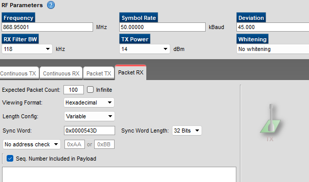
很遗憾、我无法确认我的设置、但在这里找到了一条数据包应收的声明: 如何将 Smart RF Studio 配置为 T&C 模式?
1) 1)在 C 模式(和/或 T 模式)下、SmartRF Studio 中应使用哪些设置来接收从 wMBus 器件发送的数据包?
2) 2)是否可以使用 EasyLink 抽象层("EasyLink_receiveAsync")接收 wMBus (C 模式和/或 T 模式)电报?
2.1)如果是、我如何实现它?
2.2)否则、在收集器端并行使用简单 RX/TX 框架和 wMBus (数据可在更高的级别上处理)可能会是什么解决方案?
提前感谢!
