


主题中讨论的其他器件: HDC2010
您好!
我的问题是、我 使用 Power_SHUTDOWN (0、0)将 CC1310置于关断状态
我使用 GPIO 上的 IOC 唤醒、该功能 工作正常...一次...然后器件无限期保持关断状态。
在测试期间断开调试器。
任何指针都被赞赏。
下面是有关重现此问题的一些详细信息:
在我们的应用中、我们将 HDC2010传感器连接到 CC1310
HDC2010将中断引脚从高电平切换到低电平、以便在通过 I2C 准备好新的温度和湿度数据时触发
我们使用该引脚作为 CC1310的唤醒引脚、将数据传输到收集器、然后在数据采样之间进入关断状态。
采样率为每10秒一次
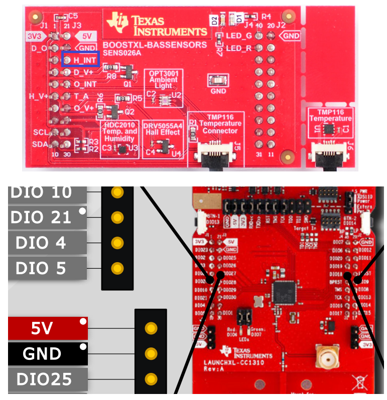
在硬件方面、我们使用 BOOSTXL-BASSENSORS 分线板与 CC1310 Launchpad
H_INT 是如图所示的唤醒引脚、它被配置为 IOID_25、因此我们知道硬件工作并且分配了正确的引脚。
在验证发生的情况方面、
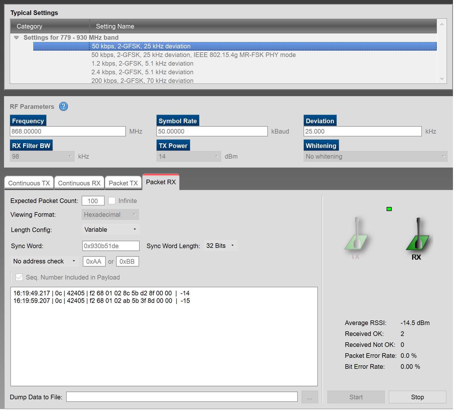
Smart RF 屏幕截图下方仅显示 收集器接收到的2个数据包
第一个数据包在发送器的第一个 POR 时、第二个数据包是第一个数据包、并且我们只能看到从关断状态唤醒。
请注意、它们之间的间隔正确为10秒
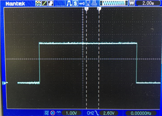
下面的 H_INT 引脚屏幕截图也显示它正确变为高电平、并在 HDC2010通电时保持高电平。
在 t=0sec 时、引脚在 HDC2010上电时变为高电平
在 t=10sec 时、变为低电平、太快、无法在宽范围时基上看到、但 CC1310正确唤醒、读取 int 状态、引脚恢复为高电平。
但是、CC1310不会在下一个采样间隔(t=20秒)唤醒
因此、总高电平持续时间为20秒。
以下是代码、
唤醒引脚在 CC1310_LAUNCHXL.h 中定义为#define BOARD_HDC_DRDY IOID_25
/*
 * Copyright (c) 2019, Texas Instruments Incorporated
 * All rights reserved.
 *
 * Redistribution and use in source and binary forms, with or without
 * modification, are permitted provided that the following conditions
 * are met:
 *
 * *  Redistributions of source code must retain the above copyright
 *    notice, this list of conditions and the following disclaimer.
 *
 * *  Redistributions in binary form must reproduce the above copyright
 *    notice, this list of conditions and the following disclaimer in the
 *    documentation and/or other materials provided with the distribution.
 *
 * *  Neither the name of Texas Instruments Incorporated nor the names of
 *    its contributors may be used to endorse or promote products derived
 *    from this software without specific prior written permission.
 *
 * THIS SOFTWARE IS PROVIDED BY THE COPYRIGHT HOLDERS AND CONTRIBUTORS "AS IS"
 * AND ANY EXPRESS OR IMPLIED WARRANTIES, INCLUDING, BUT NOT LIMITED TO,
 * THE IMPLIED WARRANTIES OF MERCHANTABILITY AND FITNESS FOR A PARTICULAR
 * PURPOSE ARE DISCLAIMED. IN NO EVENT SHALL THE COPYRIGHT OWNER OR
 * CONTRIBUTORS BE LIABLE FOR ANY DIRECT, INDIRECT, INCIDENTAL, SPECIAL,
 * EXEMPLARY, OR CONSEQUENTIAL DAMAGES (INCLUDING, BUT NOT LIMITED TO,
 * PROCUREMENT OF SUBSTITUTE GOODS OR SERVICES; LOSS OF USE, DATA, OR PROFITS;
 * OR BUSINESS INTERRUPTION) HOWEVER CAUSED AND ON ANY THEORY OF LIABILITY,
 * WHETHER IN CONTRACT, STRICT LIABILITY, OR TORT (INCLUDING NEGLIGENCE OR
 * OTHERWISE) ARISING IN ANY WAY OUT OF THE USE OF THIS SOFTWARE,
 * EVEN IF ADVISED OF THE POSSIBILITY OF SUCH DAMAGE.
 */

/***** Includes *****/
/* Standard C Libraries */
#include <stdlib.h>
#include <unistd.h>

/* TI Drivers */
#include <ti/drivers/Power.h>
#include <ti/drivers/rf/RF.h>
#include <ti/drivers/PIN.h>
#include <ti/drivers/I2C.h>
#include <ti/drivers/UART.h>
#include <ti/drivers/pin/PINCC26XX.h>

/* Driverlib Header files */
#include DeviceFamily_constructPath(driverlib/rf_prop_mailbox.h)
#include DeviceFamily_constructPath(driverlib/sys_ctrl.h)           // Needed for SysCtrlResetSourceGet()

// Hardware & Board Header files
#include "HDC2010.h"
#include "Board.h"

/* Application Header files */
#include "RFQueue.h"
#include "smartrf_settings/smartrf_settings.h"


#define HW_VER      0x01
#define FW_VER      0x02

/* Packet RX/TX Configuration */
// -----------------------------------------------------------------------------------------------------
// Defines
#define PAYLOAD_LENGTH      12                      // Max length byte the radio will accept
#define TX_DELAY          (uint32_t)(4000000*0.1f)  // Set Transmit (echo) delay to 100ms
#define PACKET_INTERVAL     500000                  // Set packet interval to 500000us or 500ms
#define NUM_DATA_ENTRIES    2                       // NOTE: Only two data entries supported at the moment
#define NUM_APPENDED_BYTES  2

// Variable declarations
static uint8_t HDC_data[4];
static uint8_t SGP_data[2];

static uint8_t txPacket[PAYLOAD_LENGTH];

// Buffer which contains all Data Entries for receiving data.
// Pragmas are needed to make sure this buffer is aligned to a 4 byte boundary (requirement from the RF core)
#pragma DATA_ALIGN(rxDataEntryBuffer, 4)
//static uint8_t rxDataEntryBuffer[RF_QUEUE_DATA_ENTRY_BUFFER_SIZE(NUM_DATA_ENTRIES,PAYLOAD_LENGTH,NUM_APPENDED_BYTES)];

static RF_Object rfObject;
static RF_Handle rfHandle;
//static rfc_propRxOutput_t rxStatistics;             // Receive Statistics
//static dataQueue_t dataQueue;                       // Receive dataQueue for RF Core to fill in data
//static rfc_dataEntryGeneral_t* currentDataEntry;
//static uint8_t packetLength;
//static uint8_t* packetDataPointer;

// Prototypes
//static void echoCallback(RF_Handle h, RF_CmdHandle ch, RF_EventMask e);

// Pre-compiler Defines
//#define LOG_RADIO_EVENTS                          // Log radio events in the callback

#ifdef LOG_RADIO_EVENTS
static volatile RF_EventMask eventLog[32];
static volatile uint8_t evIndex = 0;
#endif

const unsigned short txPowerTable[] = {
     0x0041,      //    0dBm
     0x10C3,      //    1dBm
     0x1042,      //    2dBm
     0x14C4,      //    3dBm
     0x18C5,      //    4dBm
     0x18C6,      //    5dBm
     0x1CC7,      //    6dBm
     0x20C9,      //    7dBm
     0x24CB,      //    8dBm
     0x2CCD,      //    9dBm
     0x38D3,      //   10dBm
     0x50DA,      //   11dBm
     0xB818,      //   12dBm
     0xA63F,      //   13dBm
     0xA73F,      //   14dBm
};


/* I2C Configuration */
// -----------------------------------------------------------------------------------------------------
// I2C variables
I2C_Handle          I2cHandle;
I2C_Params          I2cParams;
I2C_Transaction     i2cTransaction;


/* UART Configuration */
// -----------------------------------------------------------------------------------------------------
// Defines
#define UART_READ_DELAY   4                     // 4 seconds

// UART variables
UART_Handle uart;
UART_Params uartParams;
const char  echoPrompt[] = "Detail:";
char        input[10];
uint8_t     uartLineEndCount = 0;


/* GPIO Configuration */
// -----------------------------------------------------------------------------------------------------
// Pin driver handle
static PIN_Handle ledPinHandle;
static PIN_State ledPinState;

// LED Pin Table
PIN_Config pinTable[] =
{
    Board_PIN_LED1 | PIN_GPIO_OUTPUT_EN | PIN_GPIO_HIGH | PIN_PUSHPULL | PIN_DRVSTR_MAX,    // Grn Led initially On
    Board_PIN_LED2 | PIN_GPIO_OUTPUT_EN | PIN_GPIO_LOW | PIN_PUSHPULL | PIN_DRVSTR_MAX,     // Red Led initially off
    PIN_TERMINATE
};
// WAKE-UP Pin Table
PIN_Config pinTableWakeUp[] = {
    BOARD_HDC_DRDY | PIN_INPUT_EN | PIN_PULLUP | PIN_HYSTERESIS | PINCC26XX_WAKEUP_NEGEDGE,
    PIN_TERMINATE
};
// -----------------------------------------------------------------------------------------------------

/* Flag to store whether we woke up from shutdown or not */
bool isWakingFromShutdown;


#define SENSOR  1


// Function definitions
// *********************************************************************************************************

void *mainThread(void *arg0)
{
    // Get reason for reset - wake from shutdown, POR, etc
    uint32_t rSrc = SysCtrlResetSourceGet();
    if(rSrc == RSTSRC_WAKEUP_FROM_SHUTDOWN){
        isWakingFromShutdown = true;
    }
    else{
        isWakingFromShutdown = false;
    }


    // Open LED pins
    ledPinHandle = PIN_open(&ledPinState, pinTable);
    if (ledPinHandle == NULL)
    {
        while(1);
    }


    if(SENSOR)       // SENSOR
    {

        // I2C COMMS Configuration
        // -----------------------------------------------------------------------------------------------------
        {
            #define I2C_READ_DELAY    5000                  // Delay in us or 5ms
            uint8_t hds_status = 0;

            I2C_init();
            I2C_Params_init(&I2cParams);
            I2cParams.transferMode = I2C_MODE_BLOCKING;
            I2cParams.transferCallbackFxn = NULL;
            I2cParams.bitRate = I2C_400kHz;
            I2cHandle = I2C_open(Board_I2C0, &I2cParams);
            if(I2cHandle == NULL){
               // Error opening I2C
            }
            if(!isWakingFromShutdown)
            {
                sleep(5);
                // Waking from Reset - Initialization of HDC2010
                //HDC2010_peripheral_init();
                I2C_Read(SGP_data,HDC2010_MANUFACTURER_ID_L_REG,2);         // read Product ID (0x4954) to check I2C
                hds_status = HDC2010_config_init();                                      // setup Interrupts and measurement mode
                I2C_Write(0x01,HDC2010_MEAS_CONFIG_REG,2);                  // initiate measurement for first time
                usleep(I2C_READ_DELAY);                                     // N.B too small and DRRDy pin will remain low
                I2C_Read(SGP_data,HDC2010_DRDY_INT_STATUS_REG,1);           // clear existing interrupts
            }

            // HDC Read the 4bytes of Temperature & Relative Humidity data
            if( !I2C_Read(HDC_data,HDC2010_TEMP_REG,4) ){
                // HDC2010 Config failed, load dummy data
                HDC_data[0] = 0xFF;
                HDC_data[1] = 0xFF;
                HDC_data[2] = 0xFF;
                HDC_data[3] = 0xFF;
            }
            I2C_close(I2cHandle);
        }
        // -----------------------------------------------------------------------------------------------------


        /* Radio Packet TX Configuration */
        // -----------------------------------------------------------------------------------------------------
        {
            RF_Params rfParams;
            RF_Params_init(&rfParams);
            rfParams.nInactivityTimeout = 1000;

            RF_cmdPropTx.pktLen = PAYLOAD_LENGTH;
            RF_cmdPropTx.pPkt = txPacket;
            RF_cmdPropTx.startTrigger.triggerType = TRIG_NOW;

            /* Request access to the radio */
            RF_cmdPropRadioDivSetup.txPower =  txPowerTable[14] ;
            rfHandle = RF_open(&rfObject, &RF_prop, (RF_RadioSetup*)&RF_cmdPropRadioDivSetup, &rfParams);

            uint32_t macAddrLsb = HWREG(FCFG1_BASE + FCFG1_O_MAC_15_4_0);       // Get unique lower 16bit of IEEE MAC address as RF ID

            /* Set the frequency */
            RF_postCmd(rfHandle, (RF_Op*)&RF_cmdFs, RF_PriorityNormal, NULL, 0);
            txPacket[0] = (uint8_t)(0xA5);
            txPacket[1] = (uint8_t)(0xA5);
            txPacket[2] = (macAddrLsb);
            txPacket[3] = (macAddrLsb >> 8);
            txPacket[4] = HW_VER;
            txPacket[5] = FW_VER;
            txPacket[6] = HDC_data[0];
            txPacket[7] = HDC_data[1];
            txPacket[8] = HDC_data[2];
            txPacket[9] = HDC_data[3];
            //txPacket[8] = SGP_data[0];
            //txPacket[9] = SGP_data[1];

            /* Send packet */
            RF_EventMask rfresult = RF_runCmd(rfHandle, (RF_Op*)&RF_cmdPropTx,RF_PriorityNormal, NULL, 0);
            if (rfresult != RF_EventLastCmdDone)
            {
                while(1); // Error
            }
            /* Power down the radio */
            RF_yield(rfHandle);
        }
        // -----------------------------------------------------------------------------------------------------


        // Grn LED Off - going into shutdown
        PIN_setOutputValue(ledPinHandle, Board_PIN_LED1, 0);

        // Configure GPIO for Wake-up from Shutdown
        PINCC26XX_setWakeup(pinTableWakeUp);

        // Go to Shutdown
        Power_shutdown(0,0);

        // Should never get here!
        //PIN_setOutputValue(ledPinHandle, Board_PIN_LED1, 1);    // Grn LED On - Degging Only
        //PIN_setOutputValue(ledPinHandle, Board_PIN_LED2, 1);    // Red LED On - Degging Only

        while(1);

    }

}
