This thread has been locked.

If you have a related question, please click the "Ask a related question" button in the top right corner. The newly created question will be automatically linked to this question.

[参考译文] CC1312R7:无法通过 CCS 内的 SysConfig 为 UART1模块的 RX 和 TX 引脚交换创建有效的解决方案

Guru**** 633105 points
Other Parts Discussed in Thread: CC1312R7, LP-CC1312R7, SYSCONFIG
请注意,本文内容源自机器翻译,可能存在语法或其它翻译错误,仅供参考。如需获取准确内容,请参阅链接中的英语原文或自行翻译。

https://e2e.ti.com/support/wireless-connectivity/sub-1-ghz-group/sub-1-ghz/f/sub-1-ghz-forum/1178443/cc1312r7-unable-to-create-a-working-solution-for-swapping-rx-and-tx-pins-of-uart1-module-by-sysconfig-within-ccs

器件型号:CC1312R7
Thread 中讨论的其他部件: 、SysConfig

您好!

我使用 CC1312R7创建了自己的电路板、该电路板除其他外设外、还包含 CP2102N-A02-GQFN28R USB 收发器。 遗憾的是、我已将 MCU 的 UART_TX 连接到 USB 收发器的 UART_TX (我对 UART_RX 引脚也进行了同样的操作)。

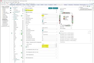
我的第一个想法是-因为我不想立刻剪断和重新接线-我可以在软件中重新映射引脚吗? 在我的项目中、我使用 了 simplelink_cc13xx_cc26xx_sdk_6_30_01_03、使用 SysConfig 创建配置。 我 正在使用 UART1外设将调试字符串发送到 PC。 我正在使用 LP-CC1312R7中的 XDS110调试器对我的硬件进行编程/调试。 我还使用具有协议解码器的逻辑分析仪来查看数据流量。 在代码中、我使用 TI 驱动程序的 Display 驱动程序(UART 模式)来利用实现的"printf"类函数。 使用 SysConfig 原始值:Display\UART\PinMux\TX 引脚= 8且  Display\UART\PinMux\RX 引脚= 7、尽管 PCB 中的接线错误、但我可以看到使用逻辑分析仪将正确的调试字符串发送到引脚8 (DIO3)。 当我将引脚映射倒转至: Display\UART\PinMux\TX 引脚= 7和 Display\UART\PinMux\RX 引脚= 8时、我可以检测到在任一 MCU 引脚上没有发送字节(我正在监控这两个引脚)。 我认为这可能是由于硬件中的布线错误造成的、因此我将 RX 和 TX 引脚配置为当前未使用的引脚、这些引脚仅连接到硬件中的测试点。 这个配置已经工作(我可以在引脚39上看到带有逻辑分析仪的字符串): Display\UART\PinMux\TX 引脚= 39 (DIO26)和 Display\UART\PinMux\RX 引脚= 40 (DIO27)。 但是、当我同时反转这两个引脚时: Display\UART\PinMux\TX 引脚= 40 (DIO27)和 Display\UART\PinMux\RX 引脚= 39 (DIO26)、使用逻辑分析仪可以在这两个引脚中的任何一个引脚上看不到任何内容。

我追溯了 SysConfig 下生成的文件的内容、它们似乎始终反映了引脚、句柄等的正确配置

我是否跳过一些关键的内容、以便某些重映射配置无法正常工作? 原因可能是什么?

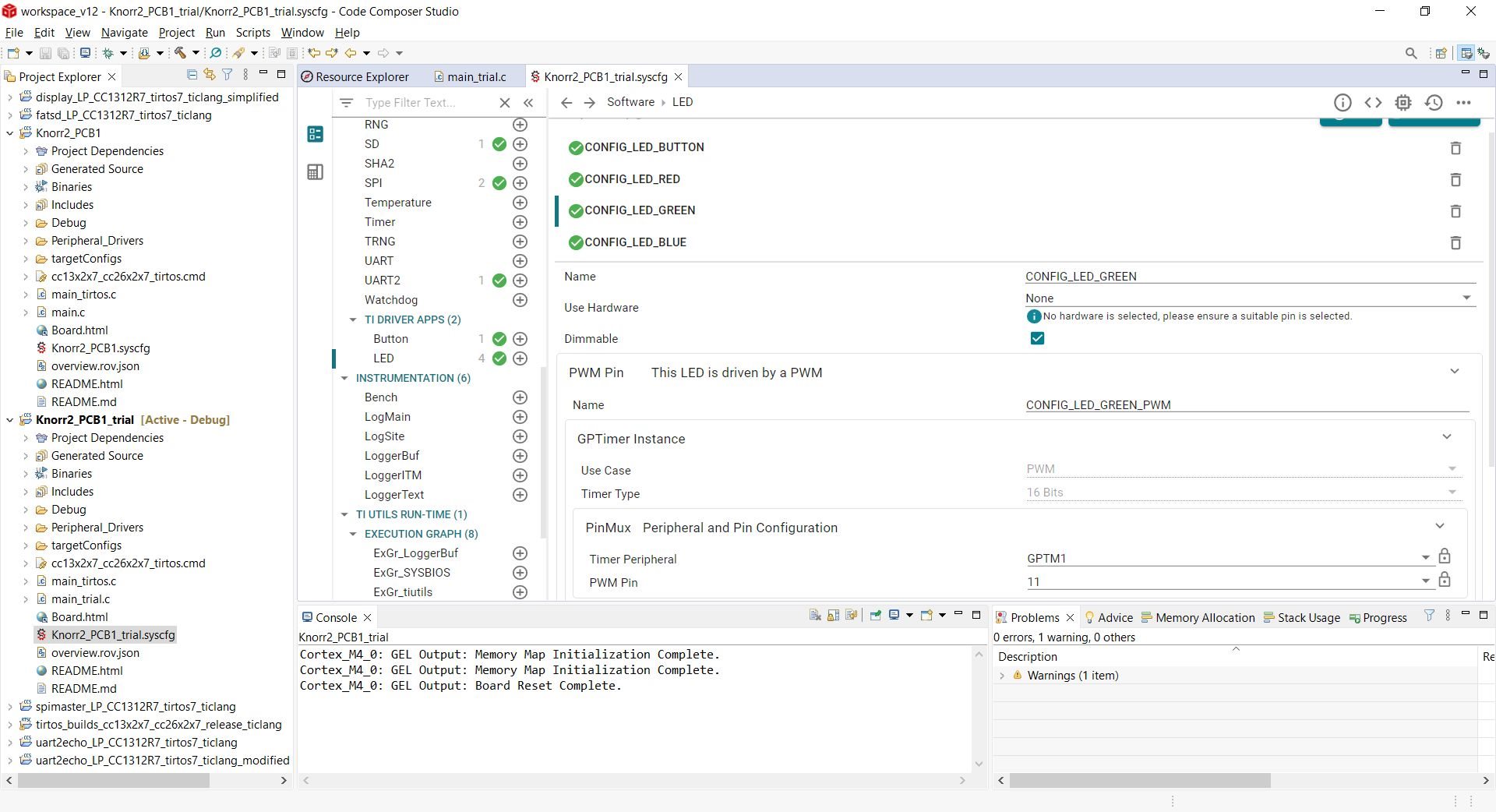
我随附了整个项目以及在工作和非工作情况下处理的所有文件。 切勿介意 main.c 中的其余代码、它只是通过 I2C (顺便说一下)向板载 RTCC IC 写入和读取一些字节。

我希望能就我应该如何解决这一问题提供一些建议。

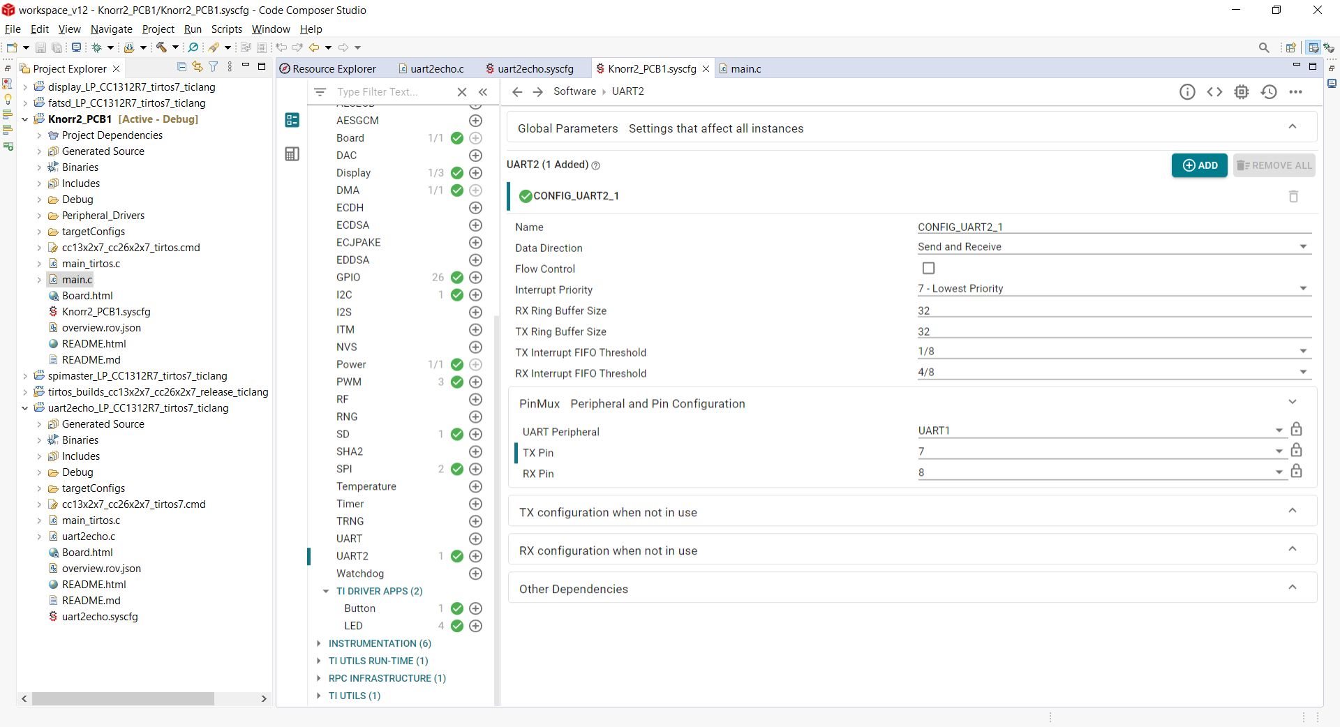
我还尝试使用 SDK 示例项目"uart2ECHO_LP_CC1312R7 tirtos7_tirang"重新映射 CC1312R7 Launchpad 硬件的 UART 引脚。 我成功了、但该示例项目不使用 TI Display 中间件。 这是否意味着我的问题也在中间件的某处?

谢谢、此致:

Balazs

e2e.ti.com/.../K2_5F00_PCB1_5F00_Doesnt_5F00_Work.zipe2e.ti.com/.../K2_5F00_PCB1_5F00_Works.zip

  • 请注意,本文内容源自机器翻译,可能存在语法或其它翻译错误,仅供参考。如需获取准确内容,请参阅链接中的英语原文或自行翻译。

    遗憾的是、我无法打开您的项目、但我使用 CC1312R7LP 和显示驱动程序(使用 UART)进行了一些测试。

    我使用了最新 SDK 中的默认显示代码示例、并将 UART 更改为使用一些可用引脚(DIO26和 DIO27)、而不是使用 XSC110 UART (DIO2和 DIO3):

    在 SysConfig 中进行了以下更改:

    我测试了以下两项:

    TX 在 DIO26上

    Rx 位于 DIO27上  

    另一种方法、并且能够监控 DIO26和 DIO27上的数据输出(TX)。

    应用代码简化如下:

    void *mainThread(void *arg0)
    {
        Display_init();
    
        Display_Params params;
        Display_Params_init(&params);
        params.lineClearMode = DISPLAY_CLEAR_BOTH;
    
    
        Display_Handle hSerial = Display_open(Display_Type_UART, &params);
    
        if (hSerial == NULL)
        {
            /* Failed to open a display */
            while (1) {}
        }
    
        while(1)
        {
            Display_printf(hSerial, 0, 0, "UUUUUUUUUUUU"); // 0x55555555------
            usleep(1000);
        }
    }

    BR

    Siri

  • 请注意,本文内容源自机器翻译,可能存在语法或其它翻译错误,仅供参考。如需获取准确内容,请参阅链接中的英语原文或自行翻译。

    您好、Siri、

    感谢您的回答、非常感谢您花时间分析此问题。

    您的方法让我有了一个想法。 我现在尝试在硬件上运行名为"uart2echo"(TI-RTOS7\TI Clang 编译器)的 SDK 示例、其中 UART 的 RX 和 TX 错误地连接到 CP2102。 我将示例代码按原样、将引脚从:UART TX = DIO3和 UART RX = DIO2更改为 UART TX = DIO2和 UART RX = DIO3、并且这些新的分配、程序在我的硬件上正确运行(回显所有字符)。 这是一个好消息、因为这意味着我的硬件可用于切换的引脚。 SysConfig 中的设置为:

    the example code's modified SysConfig

    之后我返回到我自己的代码、再次检查 SysConfig 设置并应用它们、代码不起作用。 我的代码的 SysConfig 设置为:

    My own code's SysConfig

    您可以看到、许多其他引脚和外设也在稍后进行了配置、以适应电路板的功能。 但是、此处 UART 的相关引脚与上述示例进行了相同的配置。 DIO2是 MCU 上的引脚7、DIO3是引脚8。 为什么此配置在同一硬件上不起作用、而修改后的示例代码在同一硬件上起作用?

    我已附加代码的 main.c 文件以及两个项目的 syscfg 文件的代码视图。

    非常感谢、此致:

    Balazs

    e2e.ti.com/.../2742.main.c

    /**
     * These arguments were used when this file was generated. They will be automatically applied on subsequent loads
     * via the GUI or CLI. Run CLI with '--help' for additional information on how to override these arguments.
     * @cliArgs --device "CC1312R7RGZ" --package "RGZ" --part "Default" --rtos "tirtos" --product "simplelink_cc13xx_cc26xx_sdk@6.20.00.29"
     * @versions {"tool":"1.13.0+2553"}
     */
    
    /**
     * Import the modules used in this configuration.
     */
    const CCFG     = scripting.addModule("/ti/devices/CCFG");
    const Display  = scripting.addModule("/ti/display/Display", {}, false);
    const Display1 = Display.addInstance();
    const ADC      = scripting.addModule("/ti/drivers/ADC", {}, false);
    const ADC1     = ADC.addInstance();
    const Board    = scripting.addModule("/ti/drivers/Board");
    const GPIO     = scripting.addModule("/ti/drivers/GPIO");
    const GPIO4    = GPIO.addInstance();
    const GPIO5    = GPIO.addInstance();
    const GPIO6    = GPIO.addInstance();
    const GPIO7    = GPIO.addInstance();
    const GPIO8    = GPIO.addInstance();
    const GPIO9    = GPIO.addInstance();
    const GPIO10   = GPIO.addInstance();
    const GPIO11   = GPIO.addInstance();
    const GPIO12   = GPIO.addInstance();
    const I2C      = scripting.addModule("/ti/drivers/I2C", {}, false);
    const I2C1     = I2C.addInstance();
    const Power    = scripting.addModule("/ti/drivers/Power");
    const SD       = scripting.addModule("/ti/drivers/SD", {}, false);
    const SD1      = SD.addInstance();
    const SPI      = scripting.addModule("/ti/drivers/SPI", {}, false);
    const SPI1     = SPI.addInstance();
    const SPI2     = SPI.addInstance();
    const Button   = scripting.addModule("/ti/drivers/apps/Button", {}, false);
    const Button1  = Button.addInstance();
    const LED      = scripting.addModule("/ti/drivers/apps/LED", {}, false);
    const LED1     = LED.addInstance();
    const LED2     = LED.addInstance();
    const LED3     = LED.addInstance();
    const LED4     = LED.addInstance();
    
    /**
     * Write custom configuration values to the imported modules.
     */
    CCFG.forceVddr          = true;
    CCFG.ccfgTemplate.$name = "ti_devices_CCFG_CCFGCC26XXTemplate0";
    
    Display1.$name                   = "CONFIG_Display_0";
    Display1.uart.$name              = "CONFIG_UART2_1";
    Display1.uart.uart.$assign       = "UART1";
    Display1.uart.uart.txPin.$assign = "ball.7";
    Display1.uart.uart.rxPin.$assign = "ball.8";
    
    ADC1.$name              = "CONFIG_ADC_VBAT";
    ADC1.adc.$assign        = "ADC0";
    ADC1.adc.adcPin.$assign = "ball.43";
    
    Board.generateInitializationFunctions = false;
    
    GPIO4.$name           = "CONFIG_GPIO_RTCC_INT";
    GPIO4.pull            = "Pull Up";
    GPIO4.gpioPin.$assign = "ball.32";
    
    GPIO5.$name           = "CONFIG_GPIO_BATT_M_EN";
    GPIO5.mode            = "Output";
    GPIO5.gpioPin.$assign = "ball.42";
    
    GPIO6.$name           = "CONFIG_GPIO_CHG_STAT";
    GPIO6.gpioPin.$assign = "ball.31";
    
    GPIO7.$name           = "CONFIG_GPIO_IMU_INT";
    GPIO7.pull            = "Pull Down";
    GPIO7.gpioPin.$assign = "ball.30";
    
    GPIO8.$name           = "CONFIG_GPIO_I2C1_EN";
    GPIO8.mode            = "Output";
    GPIO8.gpioPin.$assign = "ball.41";
    
    GPIO9.$name           = "CONFIG_GPIO_DIO1";
    GPIO9.mode            = "Output";
    GPIO9.gpioPin.$assign = "ball.6";
    
    GPIO10.$name           = "CONFIG_GPIO_DIO16";
    GPIO10.mode            = "Output";
    GPIO10.gpioPin.$assign = "ball.26";
    
    GPIO11.$name           = "CONFIG_GPIO_DIO17";
    GPIO11.mode            = "Output";
    GPIO11.gpioPin.$assign = "ball.27";
    
    GPIO12.$name              = "CONFIG_GPIO_SPI_IMU_CS";
    GPIO12.mode               = "Output";
    GPIO12.initialOutputState = "High";
    GPIO12.gpioPin.$assign    = "ball.20";
    
    I2C1.$name              = "CONFIG_I2C_RTCC";
    I2C1.maxBitRate         = 100;
    I2C1.i2c.$assign        = "I2C0";
    I2C1.i2c.sdaPin.$assign = "ball.10";
    I2C1.i2c.sclPin.$assign = "ball.9";
    
    SD1.$name             = "CONFIG_SD_0";
    SD1.useFatFS          = true;
    SD1.sdSSPin.$assign   = "ball.17";
    SD1.slaveSelect.$name = "CONFIG_GPIO_MEM_CS";
    
    SD1.spiInstance          = SPI1;
    SPI1.$name               = "CONFIG_SPI_MEM";
    SPI1.spi.$assign         = "SSI0";
    SPI1.spi.sclkPin.$assign = "ball.16";
    SPI1.spi.misoPin.$assign = "ball.15";
    SPI1.spi.mosiPin.$assign = "ball.14";
    
    SPI2.$name                = "CONFIG_SPI_IMU";
    SPI2.defaultTxBufferValue = "0x00";
    SPI2.minDmaTransferSize   = 1;
    SPI2.spi.$assign          = "SSI1";
    SPI2.spi.sclkPin.$assign  = "ball.21";
    SPI2.spi.misoPin.$assign  = "ball.28";
    SPI2.spi.mosiPin.$assign  = "ball.29";
    
    Button1.$name          = "CONFIG_BUTTON_0";
    Button1.pull           = "External";
    Button1.button.$assign = "ball.18";
    Button1.gpioPin.$name  = "CONFIG_GPIO_BUTTON_IN";
    Button1.gpioPin.pull   = "Pull Up";
    
    LED1.$name          = "CONFIG_LED_BUTTON";
    LED1.ledPin.$assign = "ball.19";
    
    LED2.dimmable                                = true;
    LED2.$name                                   = "CONFIG_LED_RED";
    LED2.pwmPin.timerObject.$name                = "CONFIG_GPTIMER_0";
    LED2.pwmPin.timerObject.timer.$assign        = "GPTM2";
    LED2.pwmPin.timerObject.timer.pwmPin.$assign = "ball.38";
    LED2.pwmPin.timerObject.pwmPinInstance.$name = "CONFIG_GPIO_PWM_RED";
    
    LED3.$name                                   = "CONFIG_LED_GREEN";
    LED3.dimmable                                = true;
    LED3.pwmPin.timerObject.$name                = "CONFIG_GPTIMER_1";
    LED3.pwmPin.timerObject.timer.$assign        = "GPTM0";
    LED3.pwmPin.timerObject.timer.pwmPin.$assign = "ball.11";
    LED3.pwmPin.timerObject.pwmPinInstance.$name = "CONFIG_GPIO_PWM_GREEN";
    
    LED4.$name                                   = "CONFIG_LED_BLUE";
    LED4.dimmable                                = true;
    LED4.pwmPin.timerObject.$name                = "CONFIG_GPTIMER_2";
    LED4.pwmPin.timerObject.timer.$assign        = "GPTM1";
    LED4.pwmPin.timerObject.timer.pwmPin.$assign = "ball.12";
    LED4.pwmPin.timerObject.pwmPinInstance.$name = "CONFIG_GPIO_PWM_BLUE";
    
    /**
     * Pinmux solution for unlocked pins/peripherals. This ensures that minor changes to the automatic solver in a future
     * version of the tool will not impact the pinmux you originally saw.  These lines can be completely deleted in order to
     * re-solve from scratch.
     */
    SPI1.spi.dmaRxChannel.$suggestSolution = "DMA_CH3";
    SPI1.spi.dmaTxChannel.$suggestSolution = "DMA_CH4";
    SPI2.spi.dmaRxChannel.$suggestSolution = "DMA_CH16";
    SPI2.spi.dmaTxChannel.$suggestSolution = "DMA_CH17";
    
    /**
     * These arguments were used when this file was generated. They will be automatically applied on subsequent loads
     * via the GUI or CLI. Run CLI with '--help' for additional information on how to override these arguments.
     * @cliArgs --board "/ti/boards/LP_CC1312R7" --rtos "tirtos7" --product "simplelink_cc13xx_cc26xx_sdk@6.30.01.03"
     * @versions {"tool":"1.14.0+2667"}
     */
    
    /**
     * Import the modules used in this configuration.
     */
    const Board       = scripting.addModule("/ti/drivers/Board");
    const GPIO        = scripting.addModule("/ti/drivers/GPIO");
    const GPIO1       = GPIO.addInstance();
    const UART2       = scripting.addModule("/ti/drivers/UART2");
    const UART21      = UART2.addInstance();
    const Settings    = scripting.addModule("/ti/posix/tirtos/Settings");
    const BIOS        = scripting.addModule("/ti/sysbios/BIOS");
    const Event       = scripting.addModule("/ti/sysbios/knl/Event");
    const Idle        = scripting.addModule("/ti/sysbios/knl/Idle", {}, false);
    const Idle2       = Idle.addInstance();
    const Mailbox     = scripting.addModule("/ti/sysbios/knl/Mailbox");
    const Error       = scripting.addModule("/ti/sysbios/runtime/Error");
    const SysCallback = scripting.addModule("/ti/sysbios/runtime/SysCallback");
    const Timestamp   = scripting.addModule("/ti/sysbios/runtime/Timestamp");
    
    /**
     * Write custom configuration values to the imported modules.
     */
    Board.generateInitializationFunctions = false;
    
    GPIO1.$name           = "CONFIG_GPIO_LED_0";
    GPIO1.gpioPin.$assign = "boosterpack.38";
    scripting.suppress("Connected to hardware,@@@.+?@@@ is connected to MX25R8035F SPI Flash Chip Select on the CC1312R7 LaunchPad\\. Consider selecting it in 'use hardware' above\\. @@@.+?@@@", GPIO1, "gpioPin");
    
    UART21.$name              = "CONFIG_UART2_0";
    UART21.uart.$assign       = "UART1";
    UART21.uart.txPin.$assign = "boosterpack.3";
    UART21.uart.rxPin.$assign = "boosterpack.4";
    scripting.suppress("Connected to hardware,@@@.+?@@@ is connected to XDS110 UART on the CC1312R7 LaunchPad\\. Consider selecting it in 'use hardware' above\\. @@@.+?@@@", UART21.uart, "txPin");
    scripting.suppress("Connected to hardware,@@@.+?@@@ is connected to XDS110 UART on the CC1312R7 LaunchPad\\. Consider selecting it in 'use hardware' above\\. @@@.+?@@@", UART21.uart, "rxPin");
    
    const CCFG              = scripting.addModule("/ti/devices/CCFG", {}, false);
    CCFG.ccfgTemplate.$name = "ti_devices_CCFG_CCFGCC26XXTemplate0";
    
    BIOS.assertsEnabled = false;
    BIOS.heapBaseAddr   = "__primary_heap_start__";
    BIOS.heapEndAddr    = "__primary_heap_end__";
    
    const Hwi           = scripting.addModule("/ti/sysbios/family/arm/m3/Hwi", {}, false);
    Hwi.enableException = false;
    
    const Clock      = scripting.addModule("/ti/sysbios/knl/Clock", {}, false);
    Clock.tickPeriod = 10;
    
    const Timer = scripting.addModule("/ti/sysbios/family/arm/cc26xx/Timer", {}, false);
    
    Idle2.$name   = "powerIdle";
    Idle2.idleFxn = "Power_idleFunc";
    
    const Semaphore            = scripting.addModule("/ti/sysbios/knl/Semaphore", {}, false);
    Semaphore.supportsPriority = false;
    
    const Swi         = scripting.addModule("/ti/sysbios/knl/Swi", {}, false);
    Swi.numPriorities = 6;
    
    const Task             = scripting.addModule("/ti/sysbios/knl/Task", {}, false);
    Task.checkStackFlag    = false;
    Task.defaultStackSize  = 512;
    Task.idleTaskStackSize = 512;
    Task.numPriorities     = 6;
    
    Error.policy       = "Error_SPIN";
    Error.printDetails = false;
    
    const System           = scripting.addModule("/ti/sysbios/runtime/System", {}, false);
    System.abortFxn        = "System_abortSpin";
    System.exitFxn         = "System_exitSpin";
    System.extendedFormats = "%f";
    System.supportModule   = "SysCallback";
    
    /**
     * Pinmux solution for unlocked pins/peripherals. This ensures that minor changes to the automatic solver in a future
     * version of the tool will not impact the pinmux you originally saw.  These lines can be completely deleted in order to
     * re-solve from scratch.
     */
    Timer.rtc.$suggestSolution = "RTC0";
    

  • 请注意,本文内容源自机器翻译,可能存在语法或其它翻译错误,仅供参考。如需获取准确内容,请参阅链接中的英语原文或自行翻译。

    恐怕我无法看到问题可能是什么、 当我无法在我的末尾重现问题时、很难进行调试

    由于您能够让 UART 示例在您的硬件上工作、下一步是查看您是否也可以通过执行与我相同的步骤使显示示例工作。 如果您启动并运行了该功能、则应在 SysConfig 中进行修改(一次更改一次)以支持硬件上的其他外设。 逐步执行此操作应能让您了解哪些步骤会导致硬件故障。

    Siri

  • 请注意,本文内容源自机器翻译,可能存在语法或其它翻译错误,仅供参考。如需获取准确内容,请参阅链接中的英语原文或自行翻译。

    您好、Siri、

    感谢你的答复。

    我已将问题记录到代码中的一行:

    GPIO_setConfig(CONFIG_LED_GREEN, GPIO_CFG_OUT_STD | GPIO_CFG_OUT_LOW);

    如果这一行被注释、那么反转 TX 和 RX 引脚在我的硬件上按预期工作。 如果此行未注释、并且代码中的其他所有内容保持不变、则"显示"将不起作用。

    该线路是一款处于可调光模式的 TI LED 驱动器、具有相关和配置的 PWM 和计时器以及 I/O:

    Green LED PWM SysConfig

    我尝试将此绿色 LED 配置转换为不可调光模式、但它在使显示屏正常工作方面没有帮助。 我尝试将相关的计时器更改为 PWM、这也没有帮助。

    实际上、有一件事使显示正常工作、而 GPIO_setConfig (...) 仍在代码中:我已将代码行的顺序更改为:

        // Configure the LED pin
        GPIO_setConfig(CONFIG_LED_GREEN, GPIO_CFG_OUT_STD | GPIO_CFG_OUT_LOW);
        GPIO_setConfig(CONFIG_LED_BUTTON, GPIO_CFG_OUT_STD | GPIO_CFG_OUT_LOW);
    
        // Turn off user LED
        GPIO_write(CONFIG_LED_GREEN, CONFIG_GPIO_LED_OFF);
    
        display = Display_open(Display_Type_UART, NULL);
    	if (display == NULL)
    	{
    		while (1)
    		{
    			sleep(time);
    //			GPIO_toggle(CONFIG_LED_GREEN);
    		}
    	}

    这意味着 GPIO_setConfig 现在首先执行、之后才执行 Display_open (...) 执行。 以前、这是另一种方法。

    还有两个问题要问我:

    -为什么这两个设置步骤的顺序很重要?

    -如何(以及为什么?) GPIO_setConfig 和 Display_open (用于 UART)是否相互影响、尽管它们不应该影响?

    非常感谢、此致:

    Balazs

  • 请注意,本文内容源自机器翻译,可能存在语法或其它翻译错误,仅供参考。如需获取准确内容,请参阅链接中的英语原文或自行翻译。

    恐怕我不明白为何这点很重要。

    为了深入了解这一点、我需要使用一些代码、以便在 LP 上运行时能够显示相同的问题。

    您是否能够通过从 SDK 中获取默认显示示例并仅添加 GPIO_setConfig 来重新创建问题?

    当我有一些代码时、我可以实际调试这些代码并生成您所看到的问题、我很乐意尝试弄清楚正在发生的情况。

    我从 SysConfig 屏幕截图中看到、您使用"button"和"LED" TI 驱动程序应用来配置按钮和 LED。 您能否看到、如果您使用 GPIO 手动设置按钮和 LED、您是否获得相同的结果。 这就是我们在所有示例中所做的工作。  

    可能存在一些设置不正确的情况?

    同样、分享能让我在 LP 上重新创建问题的内容将非常有帮助。

    BR

    Siri