Other Parts Discussed in Thread: SYSCONFIG, CC1312R, CC1310, CC1190, CC1352P
请注意,本文内容源自机器翻译,可能存在语法或其它翻译错误,仅供参考。如需获取准确内容,请参阅链接中的英语原文或自行翻译。
器件型号:CC1312R 主题中讨论的其他器件: CC1310、 CC1190、SysConfig、 CC1352P
您好!
我正在尝试将采用围绕 SDK v4.x 开发的固件的基于 CC1310 + CC1190的电路板迁移到 CC1312R 和 SDK v7.x。 我在阅读了这个论坛上的有关帖子之后得出的结论是,这是可以做到的,而且相对简单。 由于 CC1312R 与 CC1310从根本上而言是引脚兼容的、因此对于晶振只需进行极小的修订。 在固件方面、我们可以从重新使用 CC13-90电路板的 TX 功率表开始。 我有以下与固件开发相关的问题:
1) 1)如何重复使用 TX 功率表? 是否应停止生成的源代码并将 txPowerTable_868_pa13的内容替换为 txPowerTable_subg_US_CC1310_CC1190?
在 CC13-90/SDK v4.x 中、使用以下 TX 功率表:
const macTxPwrVal_t txPowerTable_subg_US_CC1310_CC1190[] =
{
    {7, RF_TxPowerTable_DEFAULT_PA_ENTRY(0, 3, 0, 0) },
    {14, RF_TxPowerTable_DEFAULT_PA_ENTRY(1, 3, 0, 0) },
    {18, RF_TxPowerTable_DEFAULT_PA_ENTRY(2, 3, 0, 0) },
    {20, RF_TxPowerTable_DEFAULT_PA_ENTRY(3, 3, 0, 0) },
    {22, RF_TxPowerTable_DEFAULT_PA_ENTRY(4, 3, 0, 0) },
    {23, RF_TxPowerTable_DEFAULT_PA_ENTRY(5, 3, 0, 0) },
    {24, RF_TxPowerTable_DEFAULT_PA_ENTRY(6, 3, 0, 0) },
    {25, RF_TxPowerTable_DEFAULT_PA_ENTRY(9, 3, 0, 0) },
    {26, RF_TxPowerTable_DEFAULT_PA_ENTRY(14, 3, 0, 0) },
    RF_TxPowerTable_TERMINATION_ENTRY
};
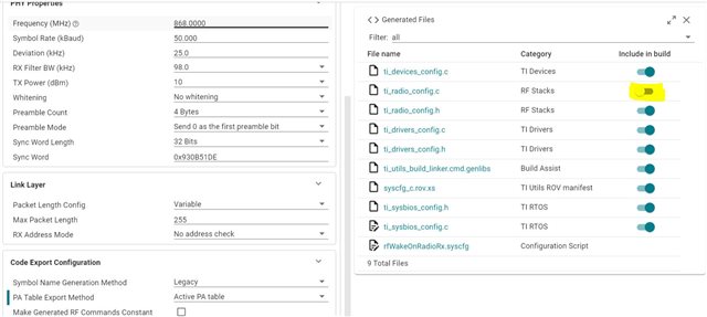
在基于 CC1312R/SDK v7.x 的工程中、生成下表:
// generated source
// ti_radio_config.c

RF_TxPowerTable_Entry txPowerTable_868_pa13[TXPOWERTABLE_868_PA13_SIZE] =
{
    {-20, RF_TxPowerTable_DEFAULT_PA_ENTRY(0, 3, 0, 2) }, // 0x04C0
    {-15, RF_TxPowerTable_DEFAULT_PA_ENTRY(1, 3, 0, 3) }, // 0x06C1
    {-10, RF_TxPowerTable_DEFAULT_PA_ENTRY(2, 3, 0, 5) }, // 0x0AC2
    {-7, RF_TxPowerTable_DEFAULT_PA_ENTRY(3, 3, 0, 5) }, // 0x0AC3
    {-5, RF_TxPowerTable_DEFAULT_PA_ENTRY(4, 3, 0, 5) }, // 0x0AC4
    {-3, RF_TxPowerTable_DEFAULT_PA_ENTRY(5, 3, 0, 6) }, // 0x0CC5
    {0, RF_TxPowerTable_DEFAULT_PA_ENTRY(8, 3, 0, 8) }, // 0x10C8
    {1, RF_TxPowerTable_DEFAULT_PA_ENTRY(9, 3, 0, 9) }, // 0x12C9
    {2, RF_TxPowerTable_DEFAULT_PA_ENTRY(10, 3, 0, 9) }, // 0x12CA
    {3, RF_TxPowerTable_DEFAULT_PA_ENTRY(11, 3, 0, 10) }, // 0x14CB
    {4, RF_TxPowerTable_DEFAULT_PA_ENTRY(13, 3, 0, 11) }, // 0x16CD
    {5, RF_TxPowerTable_DEFAULT_PA_ENTRY(14, 3, 0, 14) }, // 0x1CCE
    {6, RF_TxPowerTable_DEFAULT_PA_ENTRY(17, 3, 0, 16) }, // 0x20D1
    {7, RF_TxPowerTable_DEFAULT_PA_ENTRY(20, 3, 0, 19) }, // 0x26D4
    {8, RF_TxPowerTable_DEFAULT_PA_ENTRY(24, 3, 0, 22) }, // 0x2CD8
    {9, RF_TxPowerTable_DEFAULT_PA_ENTRY(28, 3, 0, 31) }, // 0x3EDC
    {10, RF_TxPowerTable_DEFAULT_PA_ENTRY(18, 2, 0, 31) }, // 0x3E92
    {11, RF_TxPowerTable_DEFAULT_PA_ENTRY(26, 2, 0, 51) }, // 0x669A
    {12, RF_TxPowerTable_DEFAULT_PA_ENTRY(16, 0, 0, 82) }, // 0xA410
    // The original PA value (12.5 dBm) has been rounded to an integer value.
    {13, RF_TxPowerTable_DEFAULT_PA_ENTRY(36, 0, 0, 89) }, // 0xB224
    // This setting requires CCFG_FORCE_VDDR_HH = 1.
    {14, RF_TxPowerTable_DEFAULT_PA_ENTRY(63, 0, 1, 0) }, // 0x013F
    RF_TxPowerTable_TERMINATION_ENTRY
};
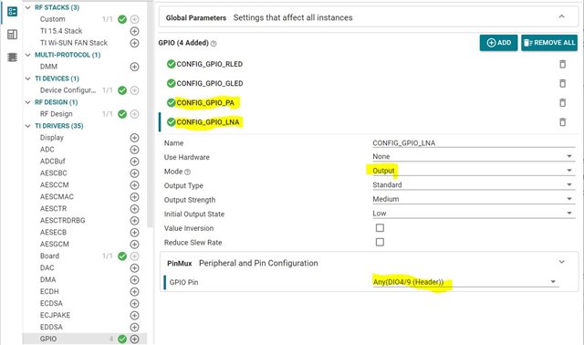
2) 2)如何初始化 CC1190?
在基于 CC13-90/SDK v4.x 的项目中、以下代码用于初始化 PA/LNA
void Board_Palna_initialize(uint32_t hgm)
{
    if (hgm)
    {
        if (!palnaPinHandle)
        {
            /* Open PA/LNA PIN driver */
            palnaPinHandle = PIN_open(&palnaPinState, palnaPinTable);

            /* Set IO muxing for RFC GPOs */
            PINCC26XX_setMux(palnaPinHandle, Board_PALNA_LNA, IOC_PORT_RFC_GPO0);
            PINCC26XX_setMux(palnaPinHandle, Board_PALNA_PA, IOC_PORT_RFC_GPO1);
        }

        PIN_setOutputValue(palnaPinHandle, Board_PALNA_HGM, (hgm & 1));

    }
}
// main.c
macUser0Cfg[0].pSetRE = Board_Palna_initialize;

// ssf.c/csf.c
/* Initialize PA/LNA if enabled */
ApiMac_mlmeSetReqUint8(ApiMac_attribute_rangeExtender, (uint8_t)CONFIG_RANGE_EXT_MODE);
在基于 CC1312R/SDK v7.x 的工程中、setRangeExtenderFp_t 不再是 macUserCfg_t 的成员:
typedef struct
{
    uint32_t               getHwRevision;     /* API to get HW revision */
    uint32_t               *pRfDrvTblPtr;     /* RF Driver API table */
    uint32_t               *pCryptoDrvTblPtr; /* Crypto Driver API table */
    alternateHalAssertFp_t pAssertFP;         /* Assert Function Pointer */
    rfSelectFp_t           pRfSelectFP;       /* RF select Function Pointer */
} macUserCfg_t;
这是否意味着我们只需调用 GPIO 函数即可将控制 CC1190的引脚设置为 main 中所需的电平?
请提供建议和谢谢。
ZL