您好!
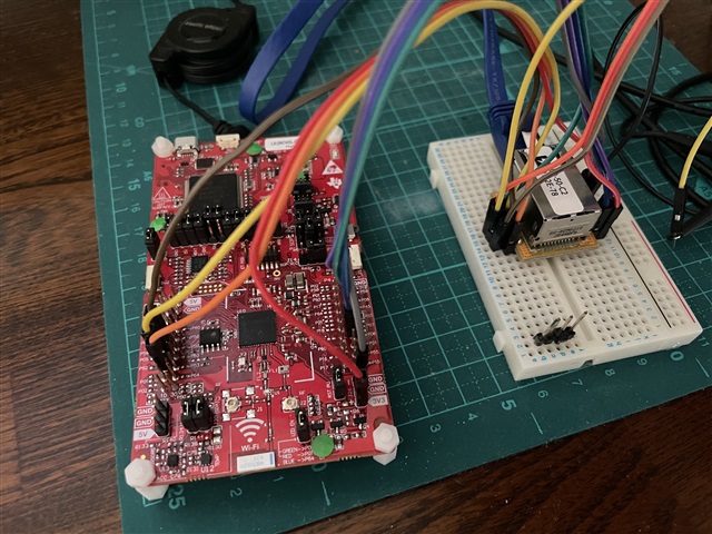
我是一名从事我的 Capstone 项目的学生。 我正在尝试在机器人项目中使用 CC3235S、其中一项功能是通过 TCP 套接字流式传输视频数据。
简而言之、我尝试从 SPI 从器件上的寄存器读取和写入值。 当使用 CC3235S 时、它始终返回错误的值、但对于 MSP432、它在使用与 TI RTOS 驱动程序基本相同的 SPI 设置时工作正常。 我不确定 CC3235S 上是否只有额外的设置、我需要进行配置以使其正确。 我通过查看示波器并在不同的微控制器上尝试相同的测试来确定它不是总线噪声。
我还尝试了 CC3235S 上的所有4个极性、但都没有结果、即使从器件数据表看起来与 POL0_PHA0完全一致。
代码
摄像机:
在某些背景下、我目前使用的是提供 SPI 接口的 T本 公司的 T本 公司的图像缓冲区数据。
数据表: https://www.arducam.com/ov2640/
摄像机 SPI 组帧:
利用此图、它似乎与 TI MCU 的 POL0_PHA0相匹配。 这适用于 MSP432、但不适用于 CC3235S

测试描述:
现在、我只是尝试将值0x55写入寄存器地址、并尝试将其读回、正如 Arduino 摄像机提供的一些示例代码中所示。 因此、在两个 MCU 上、我将尝试将0x55写入地址0x00。 根据 Arducam 文档、它将为0x80 (将位7设置为读取)用于写入、为0x00用于读取。
CC3235S 测试:
当尝试在 CC3235S 上执行此操作时、它会成功写入 C9CCam、并且相机在尝试读回总线上返回正确的值。 但在软件中、它读取的是0x33而不是0x55。
总线上的正确值;蓝色表示 MISO 线路、MOSI 表示橙色线路。 我目前无法同时探测 SCLK、因为它会使示波器和软件中的值失真。

UART 终端结果
0x33 = 51十进制

我还在 CC3235S 上尝试了多个其他值、似乎有一种将低半字节内插为4位的模式、就像对低4位进行双采样一样。
这些是尝试多个其他值的结果。
测试1:
0xAA TX
101010.
0xCC Rx
1100 1100
测试2:
0x55 TX
0101 0101
0x33 Rx
0011 0011
测试3:
0xF0 TX
1111 0000
0xFF Rx
0000 00000
测试4:
0x0F TX
0000 1111
0xFF Rx
0000 0000
测试5:
0x77 TX
0111 0111
0x3F
00 11 1111
MSP432测试:
我还有一个 msp432 launchpad、在这里我设置了相同的测试、它的工作效果非常好。
0x55 = 85十进制

CC3235S 代码:
/*
 * Copyright (c) 2018-2019, Texas Instruments Incorporated
 * All rights reserved.
 *
 * Redistribution and use in source and binary forms, with or without
 * modification, are permitted provided that the following conditions
 * are met:
 *
 * *  Redistributions of source code must retain the above copyright
 *     notice, this list of conditions and the following disclaimer.
 *
 * *  Redistributions in binary form must reproduce the above copyright
 *     notice, this list of conditions and the following disclaimer in the
 *     documentation and/or other materials provided with the distribution.
 *
 * *  Neither the name of Texas Instruments Incorporated nor the names of
 *     its contributors may be used to endorse or promote products derived
 *     from this software without specific prior written permission.
 *
 * THIS SOFTWARE IS PROVIDED BY THE COPYRIGHT HOLDERS AND CONTRIBUTORS "AS IS"
 * AND ANY EXPRESS OR IMPLIED WARRANTIES, INCLUDING, BUT NOT LIMITED TO,
 * THE IMPLIED WARRANTIES OF MERCHANTABILITY AND FITNESS FOR A PARTICULAR
 * PURPOSE ARE DISCLAIMED. IN NO EVENT SHALL THE COPYRIGHT OWNER OR
 * CONTRIBUTORS BE LIABLE FOR ANY DIRECT, INDIRECT, INCIDENTAL, SPECIAL,
 * EXEMPLARY, OR CONSEQUENTIAL DAMAGES (INCLUDING, BUT NOT LIMITED TO,
 * PROCUREMENT OF SUBSTITUTE GOODS OR SERVICES; LOSS OF USE, DATA, OR PROFITS;
 * OR BUSINESS INTERRUPTION) HOWEVER CAUSED AND ON ANY THEORY OF LIABILITY,
 * WHETHER IN CONTRACT, STRICT LIABILITY, OR TORT (INCLUDING NEGLIGENCE OR
 * OTHERWISE) ARISING IN ANY WAY OUT OF THE USE OF THIS SOFTWARE,
 * EVEN IF ADVISED OF THE POSSIBILITY OF SUCH DAMAGE.
 */

/*
 *  ======== spimaster.c ========
 */
#include <stddef.h>
#include <stdint.h>
#include <string.h>

/* POSIX Header files */
#include <pthread.h>
#include <semaphore.h>
#include <unistd.h>

/* Driver Header files */
#include <ti/drivers/GPIO.h>
#include <ti/drivers/SPI.h>
#include <ti/display/Display.h>

/* Driver configuration */
#include "ti_drivers_config.h"

#define THREADSTACKSIZE (1024)

#define SPI_MSG_LENGTH  (2)
#define MASTER_MSG      ("Hello from master, msg#: ")

#define MAX_LOOP        (10)

static Display_Handle display;

unsigned char masterRxBuffer[SPI_MSG_LENGTH] = {0x00,0x00};
unsigned char masterTxBuffer[SPI_MSG_LENGTH] = {0x80,0x55};

/* Semaphore to block master until slave is ready for transfer */
sem_t masterSem;

/*
 *  ======== slaveReadyFxn ========
 *  Callback function for the GPIO interrupt on CONFIG_SPI_SLAVE_READY.
 */
void slaveReadyFxn(uint_least8_t index)
{
    sem_post(&masterSem);
}

/*
 *  ======== masterThread ========
 *  Master SPI sends a message to slave while simultaneously receiving a
 *  message from the slave.
 */
void *masterThread(void *arg0)
{
    SPI_Handle      masterSpi;
    SPI_Params      spiParams;
    SPI_Transaction transaction;
    uint32_t        i;
    bool            transferOK;
    int32_t         status;

    /*
     * CONFIG_SPI_MASTER_READY & CONFIG_SPI_SLAVE_READY are GPIO pins connected
     * between the master & slave.  These pins are used to synchronize
     * the master & slave applications via a small 'handshake'.  The pins
     * are later used to synchronize transfers & ensure the master will not
     * start a transfer until the slave is ready.  These pins behave
     * differently between spimaster & spislave examples:
     *
     * spimaster example:
     *     * CONFIG_SPI_MASTER_READY is configured as an output pin.  During the
     *       'handshake' this pin is changed from low to high output.  This
     *       notifies the slave the master is ready to run the application.
     *       Afterwards, the pin is used by the master to notify the slave it
     *       has opened CONFIG_SPI_MASTER.  When CONFIG_SPI_MASTER is opened, this
     *       pin will be pulled low.
     *
     *     * CONFIG_SPI_SLAVE_READY is configured as an input pin. During the
     *       'handshake' this pin is read & a high value will indicate the slave
     *       ready to run the application.  Afterwards, a falling edge interrupt
     *       will be configured on this pin.  When the slave is ready to perform
     *       a transfer, it will pull this pin low.
     *
     * Below we set CONFIG_SPI_MASTER_READY & CONFIG_SPI_SLAVE_READY initial
     * conditions for the 'handshake'.
     */
//    GPIO_setConfig(CONFIG_SPI_MASTER_READY, GPIO_CFG_OUTPUT | GPIO_CFG_OUT_LOW);
//    GPIO_setConfig(CONFIG_SPI_SLAVE_READY, GPIO_CFG_INPUT);
//
//    /*
//     * Handshake - Set CONFIG_SPI_MASTER_READY high to indicate master is ready
//     * to run.  Wait CONFIG_SPI_SLAVE_READY to be high.
//     */
//    GPIO_write(CONFIG_SPI_MASTER_READY, 1);
//    while (GPIO_read(CONFIG_SPI_SLAVE_READY) == 0) {}
//
//    /* Handshake complete; now configure interrupt on CONFIG_SPI_SLAVE_READY */
//    GPIO_setConfig(CONFIG_SPI_SLAVE_READY, GPIO_CFG_IN_PU | GPIO_CFG_IN_INT_FALLING);
//    GPIO_setCallback(CONFIG_SPI_SLAVE_READY, slaveReadyFxn);
//    GPIO_enableInt(CONFIG_SPI_SLAVE_READY);

    /* Open SPI as master (default) */
    SPI_Params_init(&spiParams);
    spiParams.frameFormat = SPI_POL0_PHA0;
    spiParams.bitRate = 4000000;
    spiParams.dataSize = 8;
    masterSpi = SPI_open(CONFIG_SPI_MASTER, &spiParams);
    if (masterSpi == NULL) {
        Display_printf(display, 0, 0, "Error initializing master SPI\n");
        while (1);
    }
    else {
        Display_printf(display, 0, 0, "Master SPI initialized\n");
    }

    while(1){

            /* Initialize master SPI transaction structure */
            GPIO_write(CONFIG_GPIO_0, 0); //CS low
            masterTxBuffer[1] = 0x55;
            masterTxBuffer[0] = 0x80;
            transaction.count = 2;
            transaction.txBuf = (void *) masterTxBuffer;
            transaction.rxBuf = (void *) masterRxBuffer;

            /* Perform SPI transfer */
            transferOK = SPI_transfer(masterSpi, &transaction);
            if (transferOK) {
                Display_printf(display, 0, 0, "\nMaster received: %d", masterRxBuffer[1]);
            }
            else {
                Display_printf(display, 0, 0, "Unsuccessful master SPI transfer");
            }
            GPIO_write(CONFIG_GPIO_0, 1); //CS high
            GPIO_write(CONFIG_GPIO_0, 0); //CS low
            /* Initialize master SPI transaction structure */
            masterTxBuffer[1] = 0x00;
            masterTxBuffer[0] = 0x00;
            transaction.count = 2;
            transaction.txBuf = (void *) masterTxBuffer;
            transaction.rxBuf = (void *) masterRxBuffer;

            /* Perform SPI transfer */
            transferOK = SPI_transfer(masterSpi, &transaction);
            if (transferOK) {
                Display_printf(display, 0, 0, "\nMaster received: %d", masterRxBuffer[1]);
            }
            else {
                Display_printf(display, 0, 0, "Unsuccessful master SPI transfer");
            }
            GPIO_write(CONFIG_GPIO_0, 1); //CS high

    }

    SPI_close(masterSpi);
//
//    /* Example complete - set pins to a known state */
//    GPIO_disableInt(CONFIG_SPI_SLAVE_READY);
//    GPIO_setConfig(CONFIG_SPI_SLAVE_READY, GPIO_CFG_OUTPUT | GPIO_CFG_OUT_LOW);
//    GPIO_write(CONFIG_SPI_MASTER_READY, 0);

    Display_printf(display, 0, 0, "\nDone");

    return (NULL);
}

/*
 *  ======== mainThread ========
 */
void *mainThread(void *arg0)
{
    pthread_t           thread0;
    pthread_attr_t      attrs;
    struct sched_param  priParam;
    int                 retc;
    int                 detachState;

    /* Call driver init functions. */
    Display_init();
    GPIO_init();
    SPI_init();

    /* Open the display for output */
    display = Display_open(Display_Type_UART, NULL);
    if (display == NULL) {
        /* Failed to open display driver */
        while (1);
    }

    Display_printf(display, 0, 0, "Starting the SPI master example");
    Display_printf(display, 0, 0, "This example requires external wires to be "
        "connected to the header pins. Please see the Board.html for details.\n");

    GPIO_write(CONFIG_GPIO_0, 1);

    /* Create application threads */
    pthread_attr_init(&attrs);

    detachState = PTHREAD_CREATE_DETACHED;
    /* Set priority and stack size attributes */
    retc = pthread_attr_setdetachstate(&attrs, detachState);
    if (retc != 0) {
        /* pthread_attr_setdetachstate() failed */
        while (1);
    }

    retc |= pthread_attr_setstacksize(&attrs, THREADSTACKSIZE);
    if (retc != 0) {
        /* pthread_attr_setstacksize() failed */
        while (1);
    }

    /* Create master thread */
    priParam.sched_priority = 1;
    pthread_attr_setschedparam(&attrs, &priParam);

    retc = pthread_create(&thread0, &attrs, masterThread, NULL);
    if (retc != 0) {
        /* pthread_create() failed */
        while (1);
    }

    return (NULL);
}
MSP432代码:
/*
 * Copyright (c) 2018-2019, Texas Instruments Incorporated
 * All rights reserved.
 *
 * Redistribution and use in source and binary forms, with or without
 * modification, are permitted provided that the following conditions
 * are met:
 *
 * *  Redistributions of source code must retain the above copyright
 *     notice, this list of conditions and the following disclaimer.
 *
 * *  Redistributions in binary form must reproduce the above copyright
 *     notice, this list of conditions and the following disclaimer in the
 *     documentation and/or other materials provided with the distribution.
 *
 * *  Neither the name of Texas Instruments Incorporated nor the names of
 *     its contributors may be used to endorse or promote products derived
 *     from this software without specific prior written permission.
 *
 * THIS SOFTWARE IS PROVIDED BY THE COPYRIGHT HOLDERS AND CONTRIBUTORS "AS IS"
 * AND ANY EXPRESS OR IMPLIED WARRANTIES, INCLUDING, BUT NOT LIMITED TO,
 * THE IMPLIED WARRANTIES OF MERCHANTABILITY AND FITNESS FOR A PARTICULAR
 * PURPOSE ARE DISCLAIMED. IN NO EVENT SHALL THE COPYRIGHT OWNER OR
 * CONTRIBUTORS BE LIABLE FOR ANY DIRECT, INDIRECT, INCIDENTAL, SPECIAL,
 * EXEMPLARY, OR CONSEQUENTIAL DAMAGES (INCLUDING, BUT NOT LIMITED TO,
 * PROCUREMENT OF SUBSTITUTE GOODS OR SERVICES; LOSS OF USE, DATA, OR PROFITS;
 * OR BUSINESS INTERRUPTION) HOWEVER CAUSED AND ON ANY THEORY OF LIABILITY,
 * WHETHER IN CONTRACT, STRICT LIABILITY, OR TORT (INCLUDING NEGLIGENCE OR
 * OTHERWISE) ARISING IN ANY WAY OUT OF THE USE OF THIS SOFTWARE,
 * EVEN IF ADVISED OF THE POSSIBILITY OF SUCH DAMAGE.
 */

/*
 *  ======== spimaster.c ========
 */
#include <stddef.h>
#include <stdint.h>
#include <string.h>

/* POSIX Header files */
#include <pthread.h>
#include <semaphore.h>
#include <unistd.h>

/* Driver configuration */
#include "ti_drivers_config.h"

/* Driver Header files */
#include <ti/drivers/GPIO.h>
#include <ti/drivers/SPI.h>
#include <ti/display/Display.h>
#include <ti/drivers/Power.h>
#include <ti/drivers/power/PowerMSP432.h>

#define THREADSTACKSIZE (1024)

#define SPI_MSG_LENGTH  (30)
#define MASTER_MSG      ("Hello from master, msg#: ")

#define MAX_LOOP        (10)

static Display_Handle display;

unsigned char masterRxBuffer[SPI_MSG_LENGTH];
unsigned char masterTxBuffer[SPI_MSG_LENGTH];

/* Semaphore to block master until slave is ready for transfer */
sem_t masterSem;

/*
 *  ======== slaveReadyFxn ========
 *  Callback function for the GPIO interrupt on CONFIG_SPI_SLAVE_READY.
 */
void slaveReadyFxn(uint_least8_t index)
{
    sem_post(&masterSem);
}

/*
 *  ======== masterThread ========
 *  Master SPI sends a message to slave while simultaneously receiving a
 *  message from the slave.
 */
void *masterThread(void *arg0)
{
    SPI_Handle      masterSpi;
    SPI_Params      spiParams;
    SPI_Transaction transaction;
    uint32_t        i;
    bool            transferOK;
    int32_t         status;


    /* Open SPI as master (default) */
    SPI_Params_init(&spiParams);
    spiParams.frameFormat = SPI_POL0_PHA0;
    spiParams.bitRate = 4000000;
    masterSpi = SPI_open(CONFIG_SPI_MASTER, &spiParams);
    if (masterSpi == NULL) {
        Display_printf(display, 0, 0, "Error initializing master SPI\n");
        while (1);
    }
    else {
        Display_printf(display, 0, 0, "Master SPI initialized\n");
    }

    /* Copy message to transmit buffer */
    strncpy((char *) masterTxBuffer, MASTER_MSG, SPI_MSG_LENGTH);

    while(1){

            /* Initialize master SPI transaction structure */
            GPIO_write(CONFIG_GPIO_0, 0); //CS low
            masterTxBuffer[1] = 0x55;
            masterTxBuffer[0] = 0x80;
            transaction.count = 2;
            transaction.txBuf = (void *) masterTxBuffer;
            transaction.rxBuf = (void *) masterRxBuffer;

            /* Perform SPI transfer */
            transferOK = SPI_transfer(masterSpi, &transaction);
            if (transferOK) {
//                Display_printf(display, 0, 0, "\nMaster received: %d", masterRxBuffer[1]);
            }
            else {
                Display_printf(display, 0, 0, "Unsuccessful master SPI transfer");
            }
            GPIO_write(CONFIG_GPIO_0, 1); //CS high

            /* Initialize master SPI transaction structure */
            GPIO_write(CONFIG_GPIO_0, 0); //CS low
            masterTxBuffer[1] = 0x00;
            masterTxBuffer[0] = 0x00;
            transaction.count = 2;
            transaction.txBuf = (void *) masterTxBuffer;
            transaction.rxBuf = (void *) masterRxBuffer;

            /* Perform SPI transfer */
            transferOK = SPI_transfer(masterSpi, &transaction);
            if (transferOK) {
                Display_printf(display, 0, 0, "\nMaster received: %d", masterRxBuffer[1]);
            }
            else {
                Display_printf(display, 0, 0, "Unsuccessful master SPI transfer");
            }
            GPIO_write(CONFIG_GPIO_0, 1); //CS high

    }

    SPI_close(masterSpi);

    Display_printf(display, 0, 0, "\nDone");

    return (NULL);
}

/*
 *  ======== mainThread ========
 */
void *mainThread(void *arg0)
{
    pthread_t           thread0;
    pthread_attr_t      attrs;
    struct sched_param  priParam;
    int                 retc;
    int                 detachState;

    /* Call driver init functions. */
    Display_init();
    GPIO_init();
    SPI_init();

//    /* Configure the LED pins */
//    GPIO_setConfig(CONFIG_GPIO_LED_0, GPIO_CFG_OUT_STD | GPIO_CFG_OUT_LOW);
//    GPIO_setConfig(CONFIG_GPIO_LED_1, GPIO_CFG_OUT_STD | GPIO_CFG_OUT_LOW);

    /* Set performance level to allow custom SPI Frequency */
    Power_releaseConstraint(PowerMSP432_DISALLOW_PERFLEVEL_4);
    Power_setPerformanceLevel(4);

    /* Open the display for output */
    display = Display_open(Display_Type_UART, NULL);
    if (display == NULL) {
        /* Failed to open display driver */
        while (1);
    }

//    /* Turn on user LED */
    GPIO_write(CONFIG_GPIO_0, 1);

    Display_printf(display, 0, 0, "Starting the SPI master example");
    Display_printf(display, 0, 0, "This example requires external wires to be "
        "connected to the header pins. Please see the Board.html for details.\n");

    /* Create application threads */
    pthread_attr_init(&attrs);

    detachState = PTHREAD_CREATE_DETACHED;
    /* Set priority and stack size attributes */
    retc = pthread_attr_setdetachstate(&attrs, detachState);
    if (retc != 0) {
        /* pthread_attr_setdetachstate() failed */
        while (1);
    }

    retc |= pthread_attr_setstacksize(&attrs, THREADSTACKSIZE);
    if (retc != 0) {
        /* pthread_attr_setstacksize() failed */
        while (1);
    }

    /* Create master thread */
    priParam.sched_priority = 1;
    pthread_attr_setschedparam(&attrs, &priParam);

    retc = pthread_create(&thread0, &attrs, masterThread, NULL);
    if (retc != 0) {
        /* pthread_create() failed */
        while (1);
    }

    return (NULL);
}