Other Parts Discussed in Thread: SYSCONFIG, CC2340R5
请注意,本文内容源自机器翻译,可能存在语法或其它翻译错误,仅供参考。如需获取准确内容,请参阅链接中的英语原文或自行翻译。
器件型号:LP-EM-CC2340R53 主题中讨论的其他器件:SysConfig、 CC2340R5
工具/软件:
你(们)好
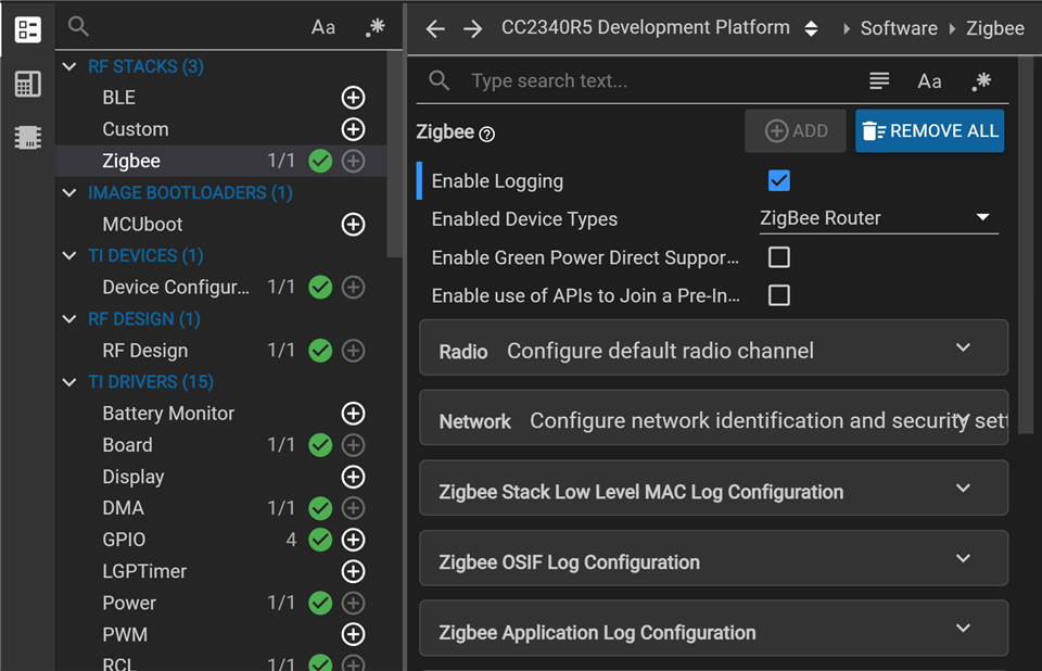
运行示例是 门锁。
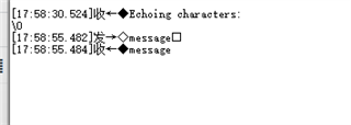
将日志的初始化添加到我的初始化过程后、它一直处于串行端口输入和输出过程中。 但是、其他 Zigbee 器件的底层逻辑无法正常工作。
期望的效果是、当串行端口上有输入时、应接收字符并执行相应的逻辑处理。 它也通过串行端口输出。 Zigbee 的逻辑也不受影响。
应如何修改?
/* door_lock.c */
#include "uart2callback.h"

MAIN()
{
  ARGV_UNUSED;

  /* Global ZBOSS initialization */
  ZB_INIT("door_lock");

  logThread(NULL); // 日志初始化
  uart2_printf("zboss_start\r\n");
  ...
}


/* uart2callback.c */

#include <stdint.h>
#include <stddef.h>

/* POSIX Header files */
#include <semaphore.h>

/* Driver Header files */
#include <ti/drivers/GPIO.h>
#include <ti/drivers/UART2.h>

/* Driver configuration */
#include "ti_drivers_config.h"
#include <stdarg.h>
#define  LOG_ENALBE

static sem_t sem;
static volatile size_t numBytesRead;

static UART2_Handle uart;

void uart2_printf(char *buffer);

/*
 *  ======== callbackFxn ========
 */
void callbackFxn(UART2_Handle handle, void *buffer, size_t count, void *userArg, int_fast16_t status)
{
     if (status != UART2_STATUS_SUCCESS)
    {
        /* RX error occured in UART2_read() */
        while (1) {}
    }

    numBytesRead = count;
    sem_post(&sem);
}

/*
 *  ======== logThread ========
 */
void *logThread(void *arg0)
{
    char input;
    const char echoPrompt[] = "Echoing characters:\r\n";
    UART2_Handle uart;
    UART2_Params uartParams;
    int32_t semStatus;
    uint32_t status = UART2_STATUS_SUCCESS;

    /* Call driver init functions */
    //GPIO_init();

    /* Configure the LED pin */
    //GPIO_setConfig(CONFIG_GPIO_LED_0, GPIO_CFG_OUT_STD | GPIO_CFG_OUT_LOW);

    /* Create semaphore */
    semStatus = sem_init(&sem, 0, 0);

    if (semStatus != 0)
    {
        /* Error creating semaphore */
        while (1) {}
    }

    /* Create a UART in CALLBACK read mode */
    UART2_Params_init(&uartParams);
    uartParams.readMode     = UART2_Mode_CALLBACK;
    uartParams.readCallback = callbackFxn;
    uartParams.baudRate     = 115200;

    uart = UART2_open(CONFIG_UART2_0, &uartParams);

    if (uart == NULL)
    {
        /* UART2_open() failed */
        while (1) {}
    }

    /* Turn on user LED to indicate successful initialization */
    //GPIO_write(CONFIG_GPIO_LED_0, CONFIG_GPIO_LED_ON);

    /* Pass NULL for bytesWritten since it's not used in this example */
    UART2_write(uart, echoPrompt, sizeof(echoPrompt), NULL);

    /* Loop forever echoing */
    while (1)
    {
        numBytesRead = 0;

        /* Pass NULL for bytesRead since it's not used in this example */
        status = UART2_read(uart, &input, 1, NULL);

        if (status != UART2_STATUS_SUCCESS)
        {
            /* UART2_read() failed */
            while (1) {}
        }

        /* Do not write until read callback executes */
        sem_wait(&sem);

        if (numBytesRead > 0)
        {
            status = UART2_write(uart, &input, 1, NULL);

            if (status != UART2_STATUS_SUCCESS)
            {
                /* UART2_write() failed */
                while (1) {}
            }
        }
    }
}

void uart2_printf(char *buffer)
{
#ifdef LOG_ENALBE
        int len=strlen(buffer);
        if(uart)
        {
                UART2_write(uart,buffer,len,NULL);
        }
#endif
}
此致、
Yongjian