

Part Number: F29H85X-SOM-EVM
Hello! Dear TI Technical Support, I'm encountering a technical issue while developing an automotive OBC using your F29 product. I'm unsure whether it's a hardware problem or a software issue on my part. The waveform is distorted when the ePWM function shifts from 100kHz to 200kHz. I consulted AI, and it explained as follows:
[In your code, the frequency jumps from 100kHz to 200kHz, meaning the value of the period register (TBPRD) is instantly halved (assuming a 100MHz clock, PRD changes from 1000 to 500). When the EPWM1 (Master) counter reaches zero-crossing (ZRO), it generates a SYNC signal, simultaneously triggering a global load on all slaves (EPWM2/3/4), updating their internal PRD, CMPA, and PHS registers. At this time, the slave's hardware counter TBCTR is forcibly written with the new phase-shift value.
] 1. During a 90° phase shift (distortion occurs): Before the transition (100kHz): PRD = 1000, PHS corresponding to 90° = 250. After the transition (200kHz): PRD = 500, PHS corresponding to 90° = 125. A microscopic event: In the nanosecond that EPWM1 reaches 0 to trigger synchronization, EPWM2 has just completed its hysteresis at a 100kHz pace, and its counter TBCTR is naturally at 250. However, the synchronization signal arrives instantaneously, and the hardware forces a new phase shift value of 125 into TBCTR. The source of the distortion: TBCTR instantly regresses from 250 back to 125! At this point, the new comparison value CMPA = 250. The counter must count upwards 125 ticks from 125 to trigger the pin level toggle (Action Qualifier). This causes the pulse width to be stretched within the transition cycle, resulting in a visible "distortion" on the oscilloscope.
2. What you are observing is not a code error or a bug in the C29x chip, but a very classic underlying physical phenomenon in digital power supply phase shift control: "Phase Shift Transient Distortion." In power electronics, this directly leads to "Volt-Second Imbalance" in the transformer.
3. Correct approach: After triggering Update_Cmd, do not directly set Target_Freq_Hz = Set_Freq_Hz. Instead, use an algorithm to change only 1kHz to 2kHz each time, smoothly transitioning to 200kHz over dozens of cycles. The smaller the step size, the smaller this TBCTR jump will be, resulting in no visible distortion on the oscilloscope and no sudden current surge in the inductor.
The above is AI's explanation. I don't know if it's accurate because I'm not the developer of the F-29 (laughs). So I'd like to ask you why this problem occurs and how to solve it?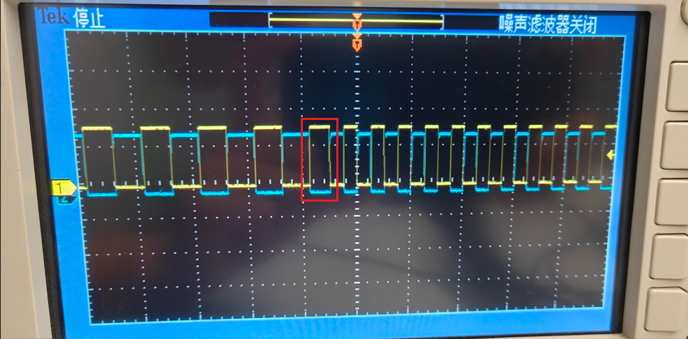

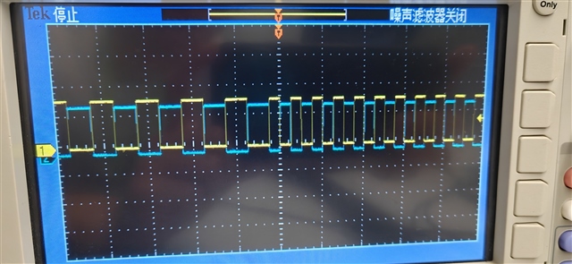 您好!尊敬的TI工程师,你可以从我目前上传的两张图进行对比,你会发现第一张图(我最开始发的图)示波器显示其中有个波形的周期短了些或长了些,这是从100k变到200k时,我用示波器捕捉到的变化时刻,黄色波形是PWM1A,蓝色波形是PWM1B,它俩为互补关系,当PWM1计数方式为up-down时,就出现第一张图的情况。如果计数方式选为up-count或zero-period就为第二张图情况,我想问问为什么会这样?是什么导致的?属不属于正常现象?同时,我试过了很多官方提供的ePWM案例,只要变频就会出现这样的情况。谢谢!