

如题,由于芯片自己的ram只有几十k,所以需要使用外部的ram,按照例程的配置。起始地址是0x300000,定义的长度为0xffff,赋值为0自增到0xffff。
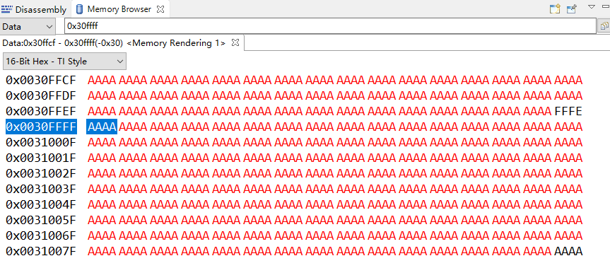
在0x300000~0x30ffff这段地址上,数据是正确的,为0~fffe。可是在地址0x30ffff往后的值也被赋值成了0~fffe。又定义另一个指针,地址位0x30ffff,长度为ffff,将这段地址赋值为aaaa,为什么地址0x300000~0x30ffff的值也被更改成了aaaa。求好心人帮助我。运行结果和代码如下:
//###########################################################################
// FILE: emif1_16bit_asram.c
// TITLE: EMIF1 module accessing 16bit ASRAM.
//
//! \addtogroup cpu01_example_list
//! <h1> EMIF ASYNC module (emif1_16bit_asram)</h1>
//!
//! This example configures EMIF1 in 16bit ASYNC mode
//! This example uses CS2 as chip enable.
//!
//! \b Watch \b Variables: \n
//! - \b TEST_STATUS - Equivalent to \b TEST_PASS if test finished correctly,
//! else the value is set to \b TEST_FAIL
//! - \b ErrCount - Error counter
//!
//
//
//###########################################################################
// $TI Release: F2837xS Support Library v180 $
// $Release Date: Fri Nov 6 16:27:58 CST 2015 $
// $Copyright: Copyright (C) 2014-2015 Texas Instruments Incorporated -
// http://www.ti.com/ ALL RIGHTS RESERVED $
//###########################################################################
#include "F28x_Project.h" // Device Headerfile and Examples Include File
#define TEST_PASS 0xABCDABCD
#define TEST_FAIL 0xDEADDEAD
#define TEST_FAIL 0xDEADDEAD
Uint16 *ExRamStart = (Uint16*)0x300000;
Uint16 *Start = (Uint16*)0x30ffff;
extern void setup_emif1_pinmux_async_16bit(Uint16);
//##########EMIF1-32bit ASRAM test ######################
#define EMIF1 0
#define EMIF2 1
#define EMIF2 1
#define MEM_D_WIDTH 1 // 16Bit Memory Interface
#define TURN_AROUND_TIME 0 // Turn Around time of 2 Emif Clock
#define RD_SETUP_TIME 0 // Read Setup time of 1 Emif Clock
#define RD_STROBE_TIME 3 // Read Strobe time of 4 Emif Clock
#define RD_HOLD_TIME 0 // Read Hold time of 1 Emif Clock
#define WR_SETUP_TIME 0 // Write Hold time of 1 Emif Clock
#define WR_STROBE_TIME 0 // Write Setup time of 1 Emif Clock
#define WR_HOLD_TIME 0 // Write Hold time of 1 Emif Clock
#define EXTEND_WAIT 0 // Disable Extended Wait
#define STROBE_SEL 0 // Disable Strobe Mode.
#define WAIT_POLAR_INV 0
#define WAIT_COUNT 0
Uint16 ErrCount = 0;
Uint32 TEST_STATUS;
int i;
void main(void)
{
// char ErrCount_local;
//TEST_STATUS = TEST_FAIL;
InitSysCtrl();
DINT;
// Initialize the PIE control registers to their default state.
// The default state is all PIE interrupts disabled and flags
// are cleared.
// This function is found in the F2837xS_PieCtrl.c file.
InitPieCtrl();
// Initialize the PIE control registers to their default state.
// The default state is all PIE interrupts disabled and flags
// are cleared.
// This function is found in the F2837xS_PieCtrl.c file.
InitPieCtrl();
// Disable CPU interrupts and clear all CPU interrupt flags:
EALLOW;
IER = 0x0000;
IFR = 0x0000;
EDIS;
// Initialize the PIE vector table with pointers to the shell Interrupt
// GService Routines (ISR).
// This will populate the entire table, even if the interrupt
// is not used in this example. This is useful for debug purposes.
// The shell ISR routines are found in F2837xS_DefaultIsr.c.
// This function is found in F2837xS_PieVect.c.
InitPieVectTable();
//Configure to run EMIF1 on full Rate (EMIF1CLK = CPU1SYSCLK)
EALLOW;
ClkCfgRegs.PERCLKDIVSEL.bit.EMIF1CLKDIV = 0x0;
EDIS;
EALLOW;
ClkCfgRegs.PERCLKDIVSEL.bit.EMIF1CLKDIV = 0x0;
EDIS;
EALLOW;
//Disable Access Protection (CPU_FETCH/CPU_WR/DMA_WR)
Emif1ConfigRegs.EMIF1ACCPROT0.all = 0x0;
if (Emif1ConfigRegs.EMIF1ACCPROT0.all != 0x0)
{
ErrCount++;
}
Emif1ConfigRegs.EMIF1ACCPROT0.all = 0x0;
if (Emif1ConfigRegs.EMIF1ACCPROT0.all != 0x0)
{
ErrCount++;
}
// Commit the configuration related to protection. Till this bit remains set
// content of EMIF1ACCPROT0 register can't be changed.
Emif1ConfigRegs.EMIF1COMMIT.all = 0x1;
if(Emif1ConfigRegs.EMIF1COMMIT.all != 0x1)
{
ErrCount++;
}
// content of EMIF1ACCPROT0 register can't be changed.
Emif1ConfigRegs.EMIF1COMMIT.all = 0x1;
if(Emif1ConfigRegs.EMIF1COMMIT.all != 0x1)
{
ErrCount++;
}
// Lock the configuration so that EMIF1COMMIT register can't be changed any more.
Emif1ConfigRegs.EMIF1LOCK.all = 0x1;
if (Emif1ConfigRegs.EMIF1LOCK.all != 1)
{
ErrCount++;
}
Emif1ConfigRegs.EMIF1LOCK.all = 0x1;
if (Emif1ConfigRegs.EMIF1LOCK.all != 1)
{
ErrCount++;
}
EDIS;
//Configure GPIO pins for EMIF1
setup_emif1_pinmux_async_16bit(0);
setup_emif1_pinmux_async_16bit(0);
//////////////////////////////////////////////
Uint32 i
for(i = 0; i< 0xFFFF; i++)
{
*(ExRamStart + i) = i;
}
asm(" ESTOP0");
for(i=0;i<0xffff;i++){
*(Start + i) = 0xaaaa;
}
asm(" ESTOP0");
while (1);
} 运行结果
运行结果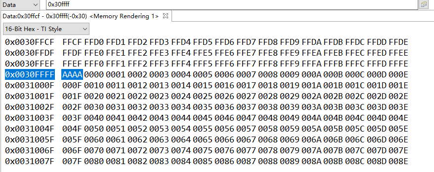
{
*(ExRamStart + i) = i;
}
asm(" ESTOP0");
for(i=0;i<0xffff;i++){
*(Start + i) = 0xaaaa;
}
asm(" ESTOP0");
while (1);
}
 运行结果
运行结果
