我需要用McBSP配置成SPI,用来与W5500通讯,但是中间有个波特率不知道怎配,请大家指点!

This thread has been locked.
If you have a related question, please click the "Ask a related question" button in the top right corner. The newly created question will be automatically linked to this question.
我需要用McBSP配置成SPI,用来与W5500通讯,但是中间有个波特率不知道怎配,请大家指点!
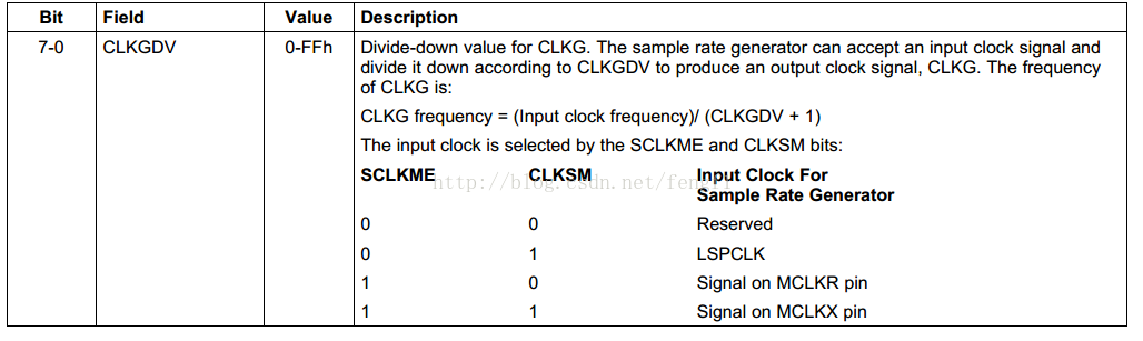
传输波特率是由CLKGDV决定,它是一个CLKG的分频数值,从0到255.
您可以看一下
另外我们有相关的例程,您可以看一下
//###########################################################################
// Description:
//! \addtogroup f2833x_example_list
//! <h1>McBSP Digital Loop Back using SPI Mode (mcbsp_spi_loopback)</h1>
//!
//! This program will execute and transmit words until terminated by the user.
//!
//! By default for the McBSP examples, the McBSP sample rate generator (SRG) input
//! clock frequency is LSPCLK (150E6/4 or 100E6/4) assuming SYSCLKOUT = 150 MHz or
//! 100 MHz respectively.  If while testing, the SRG input frequency
//! is changed, the #define MCBSP_SRG_FREQ  (CPU_SPD/4) in the Mcbsp.c file must
//! also be updated accordingly.  This define is used to determine the Mcbsp initialization
//! delay after the SRG is enabled, which must be at least 2 SRG clock cycles.
//!
//! \b Watch \b Variables \n
//! - sdata1
//! - sdata2
//! - rdata1
//! - rdata2
//
//
//###########################################################################
// $TI Release: F2833x/F2823x Header Files and Peripheral Examples V142 $
// $Release Date: November  1, 2016 $
// $Copyright: Copyright (C) 2007-2016 Texas Instruments Incorporated -
//             http://www.ti.com/ ALL RIGHTS RESERVED $
//###########################################################################

#include "DSP28x_Project.h"     // Device Headerfile and Examples Include File

// Prototype statements for functions found within this file.

void init_mcbsp_spi(void);
void mcbsp_xmit(int a, int b);
void error(void);

// Global data for this example
Uint16 sdata1 = 0x000;    // Sent Data
Uint16 rdata1 = 0x000;    // Received Data

Uint16 sdata2 = 0x000;    // Sent Data
Uint16 rdata2 = 0x000;    // Received Data

void main(void)
{
// Step 1. Initialize System Control:
// PLL, WatchDog, enable Peripheral Clocks
// This example function is found in the DSP2833x_SysCtrl.c file.
   InitSysCtrl();

// Step 2. Initialize GPIO:
// This example function is found in the DSP2833x_Gpio.c file and
// illustrates how to set the GPIO to it's default state.
// InitGpio();  // Skipped for this example
// For this example, only enable the GPIO for McBSP-A
   InitMcbspaGpio();

// Step 3. Clear all interrupts and initialize PIE vector table:
// Disable CPU interrupts
   DINT;

// Initialize PIE control registers to their default state.
// The default state is all PIE interrupts disabled and flags
// are cleared.
// This function is found in the DSP2833x_PieCtrl.c file.
   InitPieCtrl();

// Disable CPU interrupts and clear all CPU interrupt flags:
   IER = 0x0000;
   IFR = 0x0000;

// Initialize the PIE vector table with pointers to the shell Interrupt
// Service Routines (ISR).
// This will populate the entire table, even if the interrupt
// is not used in this example.  This is useful for debug purposes.
// The shell ISR routines are found in DSP2833x_DefaultIsr.c.
// This function is found in DSP2833x_PieVect.c.
   InitPieVectTable();

// Step 4. Initialize all the Device Peripherals:
// This function is found in DSP2833x_InitPeripherals.c
// InitPeripherals();     // Not required for this example

// Step 5. User specific code,
    init_mcbsp_spi();
    sdata1 = 0x55aa;
    sdata2 = 0xaa55;

// Main loop to transfer 32-bit words through MCBSP in SPI mode periodically
    for(;;)
    {
       mcbsp_xmit(sdata1,sdata2);
       while( McbspaRegs.SPCR1.bit.RRDY == 0 ) {}         // Master waits until RX data is ready
       rdata2 = McbspaRegs.DRR2.all;                      // Read DRR2 first.
       rdata1 = McbspaRegs.DRR1.all;                      // Then read DRR1 to complete receiving of data
       if((rdata2 != sdata2)&&(rdata1 != sdata1)) error( ); // Check that correct data is received.
       delay_loop();
       sdata1^=0xFFFF;
       sdata2^=0xFFFF;
       __asm("    nop");                                    // Good place for a breakpoint
    }
}


// Some Useful local functions
void error(void)
{
    __asm("     ESTOP0");  // test failed!! Stop!
    for (;;);
}

void init_mcbsp_spi()
{
     // McBSP-A register settings
    McbspaRegs.SPCR2.all=0x0000;		 // Reset FS generator, sample rate generator & transmitter
	McbspaRegs.SPCR1.all=0x0000;		 // Reset Receiver, Right justify word, Digital loopback dis.
    McbspaRegs.PCR.all=0x0F08;           //(CLKXM=CLKRM=FSXM=FSRM= 1, FSXP = 1)
    McbspaRegs.SPCR1.bit.DLB = 1;
    McbspaRegs.SPCR1.bit.CLKSTP = 2;     // Together with CLKXP/CLKRP determines clocking scheme
	McbspaRegs.PCR.bit.CLKXP = 0;		 // CPOL = 0, CPHA = 0 rising edge no delay
	McbspaRegs.PCR.bit.CLKRP = 0;
    McbspaRegs.RCR2.bit.RDATDLY=01;      // FSX setup time 1 in master mode. 0 for slave mode (Receive)
    McbspaRegs.XCR2.bit.XDATDLY=01;      // FSX setup time 1 in master mode. 0 for slave mode (Transmit)

	McbspaRegs.RCR1.bit.RWDLEN1=5;       // 32-bit word
    McbspaRegs.XCR1.bit.XWDLEN1=5;       // 32-bit word

    McbspaRegs.SRGR2.all=0x2000; 	 	 // CLKSM=1, FPER = 1 CLKG periods
    McbspaRegs.SRGR1.all= 0x000F;	     // Frame Width = 1 CLKG period, CLKGDV=16

    McbspaRegs.SPCR2.bit.GRST=1;         // Enable the sample rate generator
	delay_loop();                        // Wait at least 2 SRG clock cycles
	McbspaRegs.SPCR2.bit.XRST=1;         // Release TX from Reset
	McbspaRegs.SPCR1.bit.RRST=1;         // Release RX from Reset
    McbspaRegs.SPCR2.bit.FRST=1;         // Frame Sync Generator reset
}

void mcbsp_xmit(int a, int b)
{
    McbspaRegs.DXR2.all=b;
    McbspaRegs.DXR1.all=a;
}


//===========================================================================
// No more.
//===========================================================================