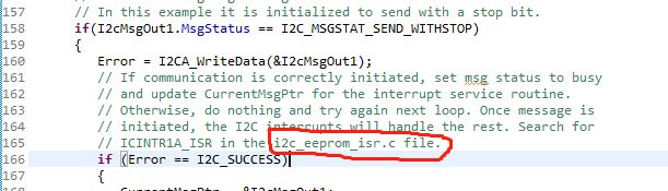
在例程C:\ti\controlSUITE\device_support\f2833x\v142\DSP2833x_examples_ccsv5\i2c_eeprom中 Example_2833xI2C_eeprom.c里面如图所示圈出来的地方所提到的i2c_eeprom_isr.c我再项目里没有找到?请问是本来就没有吗,希望得到回复,万分感谢!

This thread has been locked.
If you have a related question, please click the "Ask a related question" button in the top right corner. The newly created question will be automatically linked to this question.
在例程C:\ti\controlSUITE\device_support\f2833x\v142\DSP2833x_examples_ccsv5\i2c_eeprom中 Example_2833xI2C_eeprom.c里面如图所示圈出来的地方所提到的i2c_eeprom_isr.c我再项目里没有找到?请问是本来就没有吗,希望得到回复,万分感谢!
在例程C:\ti\controlSUITE\device_support\f2833x\v142\DSP2833x_examples_ccsv5\i2c_eeprom中 Example_2833xI2C_eeprom.c里面如图所示圈出来的地方所提到的i2c_eeprom_isr.c我再项目里没有找到?请问是本来就没有吗,希望得到回复,万分感谢!
下面相关例程请查看
//===========================================================================