This thread has been locked.

If you have a related question, please click the "Ask a related question" button in the top right corner. The newly created question will be automatically linked to this question.

F28379d通过SPI调试屏幕,连续发送数据时序出现问题

Other Parts Discussed in Thread: C2000WARE

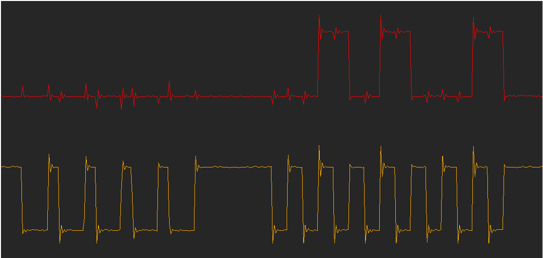
       F28379d采用c2000ware编写,通过SPI与LCD屏幕(主控ST7735)通信时,只使用了MOSI,CLK以及其他两个普通的GPIO,使能FIFO,检查软硬件都没问题,但是一直调试不通,后来单独用示波器单独抓取CLK,MOSI时序发现了问题,在发送数据的时候直接连续发送时,如下图:

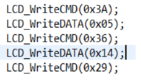
      函数内部为SPI_writeDataNonBlocking(SPIA_BASE, data<<8);这时时序出现异常,原本一共5个字节但只有最后一个字节出来了,前面的字节时钟只有4个脉冲与数据信号都没有出来

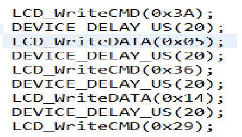
      后来试着在后面添加延时,当延时至少20us时,时序才算正常,五个字节全都出来了。

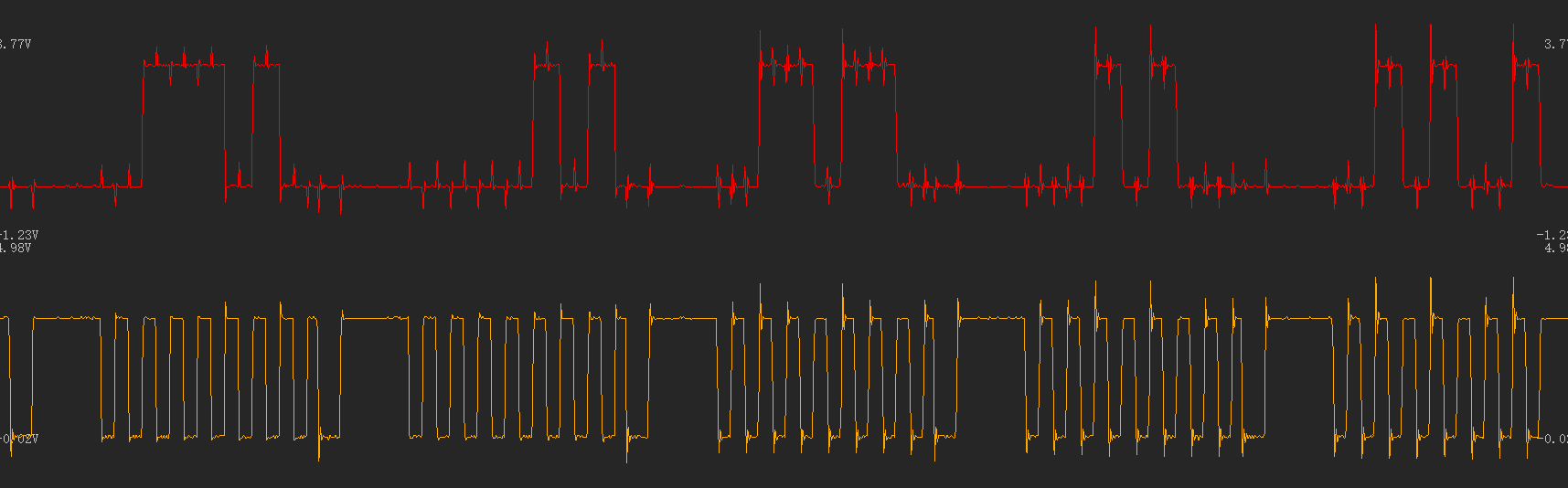
      而且这个问题不论是否使用有阻塞,有fifo的传送方式都会存在,值得注意的是在延时10us或15us时,时序出现的问题又不一样,只有最后一个字节出来,前面的数据一个字节的时钟只有4个脉冲,感觉是发送没发送完就开始了下一个字节的发送。

      但是原来使用的STM32(也是硬件SPI)都是直接这样连续发送使用的,但是移植在c2000上出现这种问题,请问这正常吗,出现异常的原因是什么,有没有方法解决

  • 请您先参考下下面的程序

    //###########################################################################
    // FILE:   Example_2837xDSpi_MasterTransmit.c
    // TITLE:  Transmit Tx data from SPI master
    //
    //!  This program transmits data from SPI master continuously. This program is configured to use on
    //!  F28379D Launchpad with modification for system clock and SPi pins.
    //!
    //!  A stream of data is sent.
    //!  The sent data looks like this: \n
    //!  0000 0001 0002 0003 0004 0005 0006 0007 .... FFFE FFFF \n
    //!  This pattern is repeated forever.
    //!
    //!  \b Watch \b Variables \n
    //!  - \b sdata - sent data
    
    #include "F28x_Project.h"     // Device Headerfile and Examples Include File
    
    // Function prototype
    void delay_loop(void);
    void spi_xmit(Uint16 a);
    void spi_fifo_init(void);
    void spi_init(void);
    void InitSpiaGpio(void);
    void InitSysCtrl1(void);
    
    Uint16 sdata = 0;  // send data
    
    void main(void)
    {
    // Initialize System Control
    // PLL, WatchDog, enable Peripheral Clocks
       InitSysCtrl1();
    
    // Initialize GPIO
       InitSpiaGpio();
    
    // Clear all __interrupts and initialize PIE vector table
    // Disable CPU __interrupts 
       DINT;
    
    // Initialize PIE control registers to their default state.
    // The default state is all PIE __interrupts disabled and flags
    // are cleared.
       InitPieCtrl();
    
    // Disable CPU __interrupts and clear all CPU __interrupt flags:
       IER = 0x0000;
       IFR = 0x0000;
       
    // Initialize the PIE vector table with pointers to the shell Interrupt 
    // Service Routines (ISR).  
    // This will populate the entire table, even if the __interrupt
    // is not used in this example.
       InitPieVectTable();
    	
    // Initialize the Device Peripherals
       spi_fifo_init();	  // Initialize the Spi FIFO
       spi_init();		  // init SPI
    
    // Transmit the data continuously
    // Interrupts are not used in this example. 
       sdata = 0x0000;							
       for(;;)
       {    
         // Transmit data
         spi_xmit(sdata);
         delay_loop();
         sdata++;
       }
    }
    
    // Local Interrupt Service Routines (ISRs) and functions
    
    void delay_loop()
    {
        long      i;
        for (i = 0; i < 1000000; i++) {}
    }
    
    void InitSysCtrl1(void)
    {
        // Disable the watchdog
        DisableDog();
    
    #ifdef _FLASH
    // Copy time critical code and Flash setup code to RAM
    // This includes the following functions:  InitFlash();
    // The  RamfuncsLoadStart, RamfuncsLoadSize, and RamfuncsRunStart
    // symbols are created by the linker. Refer to the device .cmd file.
        memcpy(&RamfuncsRunStart, &RamfuncsLoadStart, (size_t)&RamfuncsLoadSize);
    
    // Call Flash Initialization to setup flash waitstates
    // This function must reside in RAM
        InitFlash();
    #endif
    
        // *IMPORTANT*
        // The Device_cal function, which copies the ADC & oscillator calibration values
        // from TI reserved OTP into the appropriate trim registers, occurs automatically
        // in the Boot ROM. If the boot ROM code is bypassed during the debug process, the
        // following function MUST be called for the ADC and oscillators to function according
        // to specification. The clocks to the ADC MUST be enabled before calling this
        // function.
        // See the device data manual and/or the ADC Reference
        // Manual for more information.
    #ifdef CPU1
        EALLOW;
    
        //enable pull-ups on unbonded IOs as soon as possible to reduce power consumption.
        GPIO_EnableUnbondedIOPullups();
    
        CpuSysRegs.PCLKCR13.bit.ADC_A = 1;
        CpuSysRegs.PCLKCR13.bit.ADC_B = 1;
        CpuSysRegs.PCLKCR13.bit.ADC_C = 1;
        CpuSysRegs.PCLKCR13.bit.ADC_D = 1;
    
        //check if device is trimmed
        if(*((Uint16 *)0x5D1B6) == 0x0000){
            //device is not trimmed, apply static calibration values
            AnalogSubsysRegs.ANAREFTRIMA.all = 31709;
            AnalogSubsysRegs.ANAREFTRIMB.all = 31709;
            AnalogSubsysRegs.ANAREFTRIMC.all = 31709;
            AnalogSubsysRegs.ANAREFTRIMD.all = 31709;
        }
    
        CpuSysRegs.PCLKCR13.bit.ADC_A = 0;
        CpuSysRegs.PCLKCR13.bit.ADC_B = 0;
        CpuSysRegs.PCLKCR13.bit.ADC_C = 0;
        CpuSysRegs.PCLKCR13.bit.ADC_D = 0;
        EDIS;
    
        // Initialize the PLL control: PLLCR and CLKINDIV
        // F28_PLLCR and F28_CLKINDIV are defined in F2837xD_Examples.h
        // Note: The internal oscillator CANNOT be used as the PLL source if the
        // PLLSYSCLK is configured to frequencies above 194 MHz.
        InitSysPll(XTAL_OSC,40,FMULT_0,PLLCLK_BY_2);      //PLLSYSCLK = (XTAL_OSC) * (IMULT + FMULT) / (PLLSYSCLKDIV)
    #endif
    
        //Turn on all peripherals
        InitPeripheralClocks();
    }
    void spi_init()
    {
    	SpiaRegs.SPICCR.bit.SPISWRESET = 0;          // Reset on
        SpiaRegs.SPICCR.bit.SPICHAR = 15;            // 16-bit char bits
        SpiaRegs.SPICCR.bit.CLKPOLARITY = 0;         // rising edge
        SpiaRegs.SPICCR.bit.SPILBK = 0;              // Loopback disabled
    
    	SpiaRegs.SPIBRR.all =0x0063;                 // baud rate setting for master
    
    	SpiaRegs.SPICTL.bit.TALK = 1;                // enable talk
    	SpiaRegs.SPICTL.bit.SPIINTENA = 0;           // SPI int disabled
        SpiaRegs.SPICTL.bit.MASTER_SLAVE = 1;        // Master mode
        SpiaRegs.SPICTL.bit.CLK_PHASE = 1;           // delay half cycle
    
        SpiaRegs.SPICCR.bit.SPISWRESET = 1;          // Relinquish SPI from Reset
        SpiaRegs.SPIPRI.bit.FREE = 1;                // Set so breakpoints don't disturb xmission
    }
    
    void spi_xmit(Uint16 a)
    {
        if (SpiaRegs.SPIFFTX.bit.TXFFST < 16) {  //Check if TX fifo is empty before sending the data
            SpiaRegs.SPITXBUF = a;
        }
    }
    
    void spi_fifo_init()										
    {
    // Initialize SPI TX FIFO registers for now
        SpiaRegs.SPIFFTX.bit.SPIFFENA = 1;    // Enable SPI fifo
        SpiaRegs.SPIFFTX.bit.TXFIFO = 1;      // Enable Tx fifo
        SpiaRegs.SPIFFTX.bit.TXFFIL = 0;      // Tx fifo level is zero
        SpiaRegs.SPIFFTX.bit.TXFFIENA = 0;    // Disable tx fifo interrupt
        SpiaRegs.SPIFFTX.bit.TXFFINTCLR = 1;  // clear tx interrupt flag
        SpiaRegs.SPIFFTX.bit.SPIRST = 1;      // release SPI fifo TX
        SpiaRegs.SPIFFCT.all=0x0;             // TX delay = 0
    }
    
    void InitSpiaGpio()
    {
    
       EALLOW;
    
    /* Enable internal pull-up for the selected pins */
    // Pull-ups can be enabled or disabled by the user.
    // This will enable the pullups for the specified pins.
    
        GpioCtrlRegs.GPBPUD.bit.GPIO58 = 0;   // Enable pull-up on GPIO58 (SPISIMOA)
        GpioCtrlRegs.GPBPUD.bit.GPIO59 = 0;   // Enable pull-up on GPIO59 (SPISOMIA)
        GpioCtrlRegs.GPBPUD.bit.GPIO60 = 0;   // Enable pull-up on GPIO60 (SPICLKA)
        GpioCtrlRegs.GPBPUD.bit.GPIO61 = 0;   // Enable pull-up on GPIO61 (SPISTEA)
    
    /* Set qualification for selected pins to asynch only */
    // This will select asynch (no qualification) for the selected pins.
    
        GpioCtrlRegs.GPBQSEL2.bit.GPIO58 = 3; // Asynch input GPIO58 (SPISIMOA)
        GpioCtrlRegs.GPBQSEL2.bit.GPIO59 = 3; // Asynch input GPIO59 (SPISOMIA)
        GpioCtrlRegs.GPBQSEL2.bit.GPIO60 = 3; // Asynch input GPIO60 (SPICLKA)
        GpioCtrlRegs.GPBQSEL2.bit.GPIO61 = 3; // Asynch input GPIO61 (SPISTEA)
    
    /* Configure SPI-A pins using GPIO regs*/
    // This specifies which of the possible GPIO pins will be SPI functional pins.
    
        GpioCtrlRegs.GPBMUX2.bit.GPIO58 = 3; // Configure GPIO58 as SPISIMOA
        GpioCtrlRegs.GPBMUX2.bit.GPIO59 = 3; // Configure GPIO59 as SPISOMIA
        GpioCtrlRegs.GPBMUX2.bit.GPIO60 = 3; // Configure GPIO60 as SPICLKA
        GpioCtrlRegs.GPBMUX2.bit.GPIO61 = 3; // Configure GPIO61 as SPISTEA
    
        GpioCtrlRegs.GPBGMUX2.bit.GPIO58 = 3; // Configure GPIO58 as SPISIMOA
        GpioCtrlRegs.GPBGMUX2.bit.GPIO59 = 3; // Configure GPIO59 as SPISOMIA
        GpioCtrlRegs.GPBGMUX2.bit.GPIO60 = 3; // Configure GPIO60 as SPICLKA
        GpioCtrlRegs.GPBGMUX2.bit.GPIO61 = 3; // Configure GPIO61 as SPISTEA
    
        EDIS;
    }
    
    //===========================================================================
    // No more.
    //===========================================================================


  • 调用底层SPI读写函数 程序是串行执行 肯定是等待一个字节一个字节完成送出后才跳出函数
    你追踪一下函数内部执行情况,是不是没有等待或判断发送完成?