This thread has been locked.

If you have a related question, please click the "Ask a related question" button in the top right corner. The newly created question will be automatically linked to this question.

280049C CAN如何一个接收邮箱接收不同ID的数据帧

Other Parts Discussed in Thread: C2000WARE

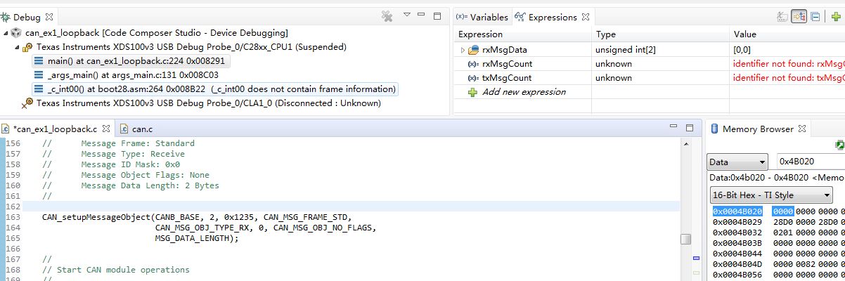
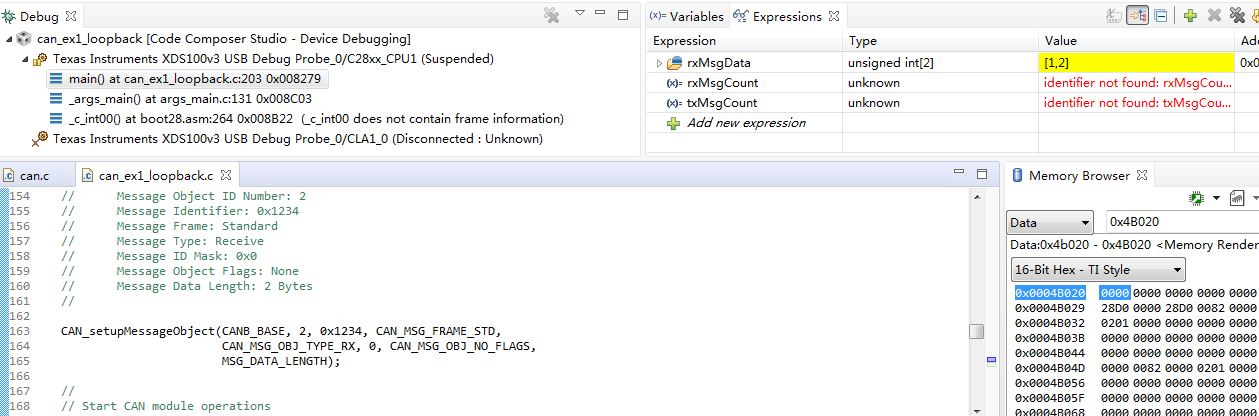
在对官方例程can_ex1_loopback.c(路径为C2000Ware_3_01_00_00\driverlib\f28004x\examples\can)仿真发现只能接收ID为0X1234的帧数据,如下图将接收邮箱的ID改为0x1235后邮箱就接收不到任何数据,将ID改为0x1234就可以接收到数据。此例程的ID Mask 为0 ,也就是掩码是没有作用的,那么想问下如何实现一个邮箱接收不同ID的数据帧,有没有相关例程参考下。谢谢!

  • 我会在测试后给您回复
  • 你好,请问测试结果怎么样?谢谢
  • 在can_ex1_loopback.c上,我的测试结果和您的相同

    在我看来是因为ext loopback即外部回环的话,如下图所示

    在此,实际上CAN消息处理程序通过IF1ABR的“ ID”设置的值来过滤消息。所以会出现您现在的情况。

    您可以参考下

  • 看了链接的回答,
    1、I set up four message object with the same obj ID and different msg ID.
    本人理解:例如对于接收邮箱2来说可以通过CAN_setupMessageObjecth函数同时设置多个不同的msg ID,这样就邮箱2就可以接收到不同ID的数据帧。
    2、CAN消息处理程序通过IF1ABR的“ ID”设置的值来过滤消息
    本人理解:就是说就算将ID Mask设置 为0,CAN消息处理程序也会将IF1ABR的“ ID”与数据帧的“ID”进行匹配,相同就会接收数据。
    请问上面的理解是否正确,谢谢。
  • 我的理解也是类似的,但还未实验成功。我会在测试成功后给您回复
  • 早上好,Susan
    1、我用C2000Ware_3_01_00_00\driverlib\f28004x\examples\can\can_ex3_external_transmit.C这个工程仿真也是只能收到ID相同的数据帧,
    2、对于链接的这句话:The mask ID filter works like this: If the message ID is 0x5555 and you set the ID mask to 0x1FFFFFFF, then only messages with ID of 0x5555 are accepted. If you set the ID mask to 0x1FFFFFF0, then message IDs 0x5550 to 0x555F are accepted.
    理解:如果ID MASK 是0x00,应该是可以接收到任何ID的数据帧,
    但是对于C2000Ware_3_01_00_00\driverlib\f28004x\examples\can\can_ex3_external_transmit.C工程仿真却不是(其ID Mask: 0x0)
    3、在对于Table 26-33. CAN_IF1ARB Register Field Descriptions 中对于Dir描述中有这么一句话:On reception of a data frame with matching identifier, that frame is stored in this message object。请问这个matching identifier是什么意思?
    4、在Table 26-34. CAN_IF1MCTL Register Field Descriptions 中对于UMask 描述:如果UMask is 0 ,Mask ignored,也就是说Umask为0 Mask是没有用的。
  • 你好,请问测试结果怎么样,谢谢。
  • 使用下面的代码可以成功了,可以接收非0x1234发出的数据了

    //#############################################################################
    //
    // FILE:   can_ex1_loopback.c
    //
    // TITLE:   CAN External Loopback Example
    //
    //! \addtogroup driver_example_list
    //! <h1> CAN External Loopback </h1>
    //!
    //! This example shows the basic setup of CAN in order to transmit and receive
    //! messages on the CAN bus.  The CAN peripheral is configured to transmit
    //! messages with a specific CAN ID.  A message is then transmitted once per
    //! second, using a simple delay loop for timing.  The message that is sent is
    //! a 2 byte message that contains an incrementing pattern.
    //!
    //! This example sets up the CAN controller in External Loopback test mode.
    //! Data transmitted is visible on the CANTXA/CANATX pin and is received internally
    //! back to the CAN Core.
    //!
    //! \b External \b Connections \n
    //!  - None.
    //!
    //! \b Watch \b Variables \n
    //!  - msgCount - A counter for the number of successful messages received
    //!  - txMsgData - An array with the data being sent
    //!  - rxMsgData - An array with the data that was received
    //!
    //
    //#############################################################################
    // $TI Release: F28004x Support Library v1.09.00.00 $
    // $Release Date: Thu Mar 19 07:26:52 IST 2020 $
    // $Copyright:
    // Copyright (C) 2020 Texas Instruments Incorporated - http://www.ti.com/
    //
    // Redistribution and use in source and binary forms, with or without 
    // modification, are permitted provided that the following conditions 
    // are met:
    // 
    //   Redistributions of source code must retain the above copyright 
    //   notice, this list of conditions and the following disclaimer.
    // 
    //   Redistributions in binary form must reproduce the above copyright
    //   notice, this list of conditions and the following disclaimer in the 
    //   documentation and/or other materials provided with the   
    //   distribution.
    // 
    //   Neither the name of Texas Instruments Incorporated nor the names of
    //   its contributors may be used to endorse or promote products derived
    //   from this software without specific prior written permission.
    // 
    // THIS SOFTWARE IS PROVIDED BY THE COPYRIGHT HOLDERS AND CONTRIBUTORS 
    // "AS IS" AND ANY EXPRESS OR IMPLIED WARRANTIES, INCLUDING, BUT NOT 
    // LIMITED TO, THE IMPLIED WARRANTIES OF MERCHANTABILITY AND FITNESS FOR
    // A PARTICULAR PURPOSE ARE DISCLAIMED. IN NO EVENT SHALL THE COPYRIGHT 
    // OWNER OR CONTRIBUTORS BE LIABLE FOR ANY DIRECT, INDIRECT, INCIDENTAL, 
    // SPECIAL, EXEMPLARY, OR CONSEQUENTIAL DAMAGES (INCLUDING, BUT NOT 
    // LIMITED TO, PROCUREMENT OF SUBSTITUTE GOODS OR SERVICES; LOSS OF USE,
    // DATA, OR PROFITS; OR BUSINESS INTERRUPTION) HOWEVER CAUSED AND ON ANY
    // THEORY OF LIABILITY, WHETHER IN CONTRACT, STRICT LIABILITY, OR TORT 
    // (INCLUDING NEGLIGENCE OR OTHERWISE) ARISING IN ANY WAY OUT OF THE USE 
    // OF THIS SOFTWARE, EVEN IF ADVISED OF THE POSSIBILITY OF SUCH DAMAGE.
    // $
    //#############################################################################
    
    //
    // Included Files
    //
    #include "driverlib.h"
    #include "device.h"
    
    //
    // Defines
    //
    #define MSG_DATA_LENGTH    2
    
    //
    // Globals
    //
    volatile unsigned long msgCount = 0;
    
    //
    // Main
    //
    void main(void)
    {
        uint16_t txMsgData[2], rxMsgData[2];
    
        //
        // Initialize device clock and peripherals
        //
        Device_init();
    
        //
        // Initialize GPIO and configure GPIO pins for CANTX/CANRX
        //
        Device_initGPIO();
        GPIO_setPinConfig(DEVICE_GPIO_CFG_CANRXA);
        GPIO_setPinConfig(DEVICE_GPIO_CFG_CANTXA);
    
        //
        // Initialize the CAN controller
        //
        CAN_initModule(CANA_BASE);
    
        //
        // Set up the CAN bus bit rate to 500kHz
        // Refer to the Driver Library User Guide for information on how to set
        // tighter timing control. Additionally, consult the device data sheet
        // for more information about the CAN module clocking.
        //
        CAN_setBitRate(CANA_BASE, DEVICE_SYSCLK_FREQ, 500000, 20);
    
        //
        // Initialize PIE and clear PIE registers. Disables CPU interrupts.
        //
        Interrupt_initModule();
    
        //
        // Initialize the PIE vector table with pointers to the shell Interrupt
        // Service Routines (ISR).
        //
        Interrupt_initVectorTable();
    
        //
        // Enable Global Interrupt (INTM) and realtime interrupt (DBGM)
        //
        EINT;
        ERTM;
    
        //
        // Enable CAN test mode with external loopback
        //
        CAN_enableTestMode(CANA_BASE, CAN_TEST_EXL);
    
        //
        // Initialize the transmit message object used for sending CAN messages.
        // Message Object Parameters:
        //      Message Object ID Number: 1
        //      Message Identifier: 0x1234
        //      Message Frame: Standard
        //      Message Type: Transmit
        //      Message ID Mask: 0x0
        //      Message Object Flags: None
        //      Message Data Length: 2 Bytes
        //
        CAN_setupMessageObject(CANA_BASE, 1, 0x1235, CAN_MSG_FRAME_STD,
                               CAN_MSG_OBJ_TYPE_TX, 0, CAN_MSG_OBJ_NO_FLAGS,
                               MSG_DATA_LENGTH);


        //
        // Initialize the receive message object used for receiving CAN messages.
        // Message Object Parameters:
        //      Message Object ID Number: 2
        //      Message Identifier: 0x1234
        //      Message Frame: Standard
        //      Message Type: Receive
        //      Message ID Mask: 0x0
        //      Message Object Flags: None
        //      Message Data Length: 2 Bytes
        //
      //  CAN_setupMessageObject(CANA_BASE, 2, 0x1234, CAN_MSG_FRAME_STD,
                            //   CAN_MSG_OBJ_TYPE_RX, 0, CAN_MSG_OBJ_NO_FLAGS,
                             //  MSG_DATA_LENGTH);
    
        CAN_setupMessageObject(CANA_BASE, 2, 0x1234, CAN_MSG_FRAME_STD,
                               CAN_MSG_OBJ_TYPE_RX, 0x00000000, CAN_MSG_OBJ_USE_ID_FILTER,
                               MSG_DATA_LENGTH);
    
        //
        // Start CAN module operations
        //
        CAN_startModule(CANA_BASE);
    
        //
        // Setup send and receive buffers
        //
        txMsgData[0] = 0x01;
        txMsgData[1] = 0x02;
        *(uint16_t *)rxMsgData = 0;
    
        //
        // Loop Forever - Send and Receive data continuously
        //
        for(;;)
        {
            //
            // Send CAN message data from message object 1
            //
            CAN_sendMessage(CANA_BASE, 1, MSG_DATA_LENGTH, txMsgData);
    
            //
            // Delay before receiving the data
            //
            DEVICE_DELAY_US(500000);
    
            //
            // Read CAN message object 2 and check for new data
            //
            if (CAN_readMessage(CANA_BASE, 2, rxMsgData))
            {
                //
                // Check that received data matches sent data.
                // Device will halt here during debug if data doesn't match.
                //
                if((txMsgData[0] != rxMsgData[0]) ||
                   (txMsgData[1] != rxMsgData[1]))
                {
                    Example_Fail = 1;
                    asm("   ESTOP0");
                }
                else
                {
                    //
                    // Increment message received counter
                    //
                    msgCount++;
                    Example_PassCount++;
                }
            }
            else
            {
                //
                // Device will halt here during debug if no new data was received.
                //
                Example_Fail = 1;
                asm(" ESTOP0");
            }
    
            //
            // Increment the value in the transmitted message data.
            //
            txMsgData[0] += 0x01;
            txMsgData[1] += 0x01;
    
            //
            // Reset data if exceeds a byte
            //
            if(txMsgData[0] > 0xFF)
            {
                txMsgData[0] = 0;
            }
            if(txMsgData[1] > 0xFF)
            {
                txMsgData[1] = 0;
            }
        }
    }
    
    //
    // End of File
    //
    

  • 谢谢,已经解决了。
  • 很高兴能帮到您

  • 能不能解释一下为什么啊?谢谢。280049的CAN系统和之前的差异真的很大。