280049 PWM1相关配置如下:
EPwm1Regs.AQCTLA.bit.CAU = AQ_CLEAR;
EPwm1Regs.AQCTLA.bit.CAD = AQ_SET;
EPwm1Regs.CMPCTL.bit.LOADAMODE = AQ_CTR_PRD;
EPwm1Regs.CMPCTL.bit.SHDWAMODE = CC_SHADOW;
EPwm1Regs.CMPCTL.bit.LOADBMODE = AQ_CTR_PRD;
EPwm1Regs.CMPCTL.bit.SHDWBMODE = CC_SHADOW;
EPwm1Regs.DBCTL2.bit.LOADDBCTLMODE = DB_CTR_PRD;
EPwm1Regs.DBCTL2.bit.SHDWDBCTLMODE = DB_SHADOW;
EPwm1Regs.DBCTL.bit.OUT_MODE = DB_FULL_ENABLE;
EPwm1Regs.DBCTL.bit.POLSEL = DB_ACTV_HIC;
EPwm1Regs.DBRED.bit.DBRED = PFC_DB_RED_CNT;
EPwm1Regs.DBFED.bit.DBFED = PFC_DB_FED_CNT;
在收到指令时刻,写寄存器EPwm1Regs.DBCTL.bit.OUTSWAP = 3;
目的:在收到指令后,在PWM CNT= DB_CTR_PRD 时使PWM1A和PWM1B的输出进行交替,
但是实际情况是,每当执行EPwm1Regs.DBCTL.bit.OUTSWAP = 3;操作时,PWM1A和PWM1B的输出就进行交替输出。所以OUTSWAP是立即生效的。
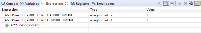
我在debug窗口下看过EPwm1Regs.DBCTL2.bit.LOADDBCTLMODE 和 EPwm1Regs.DBCTL2.bit.SHDWDBCTLMODE寄存器值的配置是正确的,截图如下:
图1:寄存器值
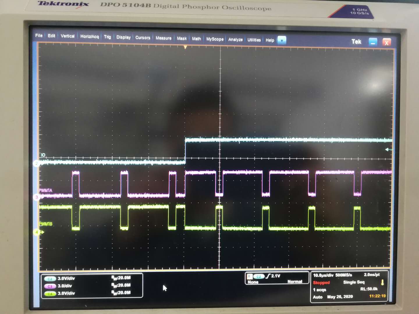
图二:PWM输出波形
2通道(蓝色)测试IO口,上升沿为EPwm1Regs.DBCTL.bit.OUTSWAP = 3;指令执行位置
3通道(紫色)PWM1A输出
4通道(绿色)PWM1B输出