我现在想采集adc2的值,用软件触发,连续采样,我的设置如下:
AdcRegs.ADCCTL1.bit.INTPULSEPOS = 0;
AdcRegs.INTSEL1N2.bit.INT2E = 0;//关闭中断
AdcRegs.INTSEL1N2.bit.INT2CONT = 1; //连续模式
AdcRegs.INTSEL1N2.bit.INT2SEL = 0x10; //选择无效
AdcRegs.ADCSOC1CTL.bit.CHSEL = 2; //将ADCINA2映射到通道1
AdcRegs.ADCSOC1CTL.bit.TRIGSEL = 0;//软件触发
//
// set SOC1 S/H Window to 7 ADC Clock Cycles, (6 ACQPS plus 1)
//
AdcRegs.ADCSOC1CTL.bit.ACQPS = 6;
EDIS;
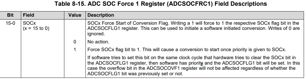
AdcRegs.ADCSOCFRC1.bit.SOC1=1;
然后我每次读的时候:
AdcRegs.ADCSOCFRC1.bit.SOC1=1;//软件触发
adc_tmp=AdcResult.ADCRESULT1;//读值
如果我改成这样:
//AdcRegs.ADCSOCFRC1.bit.SOC1=1;//软件触发
adc_tmp=AdcResult.ADCRESULT1;//读值
就读不出数来,也就是说,我把软件触发关闭,adc值就读不出来,那么这个AdcRegs.INTSEL1N2.bit.INT2CONT = 1; //连续模式有什么意义呢?如果每次我读取都需要软件触发的话,这个连续方式作用不大啊,我的理解是我把连续模式打开后,我只要软件触发一次后,我读取adc_tmp=AdcResult.ADCRESULT1;的值都会成功,因为我把连续模式打开了,如果不是这么理解的话,那么这个连续模式是怎么理解的呢?在什么情况下才有用呢?