Other Parts Discussed in Thread: C2000WARE
PWM配置:
PWM2 UP_DOWN模式,ZERO 时 SET ,PRD 时 CLR,固定50%带死区占空比输出,在 CTR=0 时发出同步信号;
PWM3 UP_DOWN模式,ZERO 时 SET ,PRD 时 CLR,固定50%带死区占空比输出;
PWM3 相对于 PWM2 进行移相,移相值固定在Phase = PRD * 0.98 范围.(0.98是为了让移相小于周期值)
timer2 产生100k的频率中断:
中断内按固定步长改变PRD值(改变PWM频率),相应地计算出新的移相值,保证PWM3和PWM的相位不变。
开启Global Load功能:
PWM2 PRD在ZERO点 由shadow载入active
PWM3 PRD在同步信号输入点 由shadow载入active
PWM3 的Phase移相值和Global Load无关,应该在同步信号输入点 由shadow载入active。
问题:
运行过程中 PWM3 会概率性出现 一个周期3A全高 3B全低的现象。
为了方便TI支持人员调试,我在C:\ti\c2000\C2000Ware_3_04_00_00\driverlib\f28004x\examples\epwm\epwm_ex3_synchronization工程上进行问题复现,只对epwm_ex3_synchronization.c进行修改
但是我不知道怎样传文件上来。如果需要复现问题,请告诉我上传的方法。
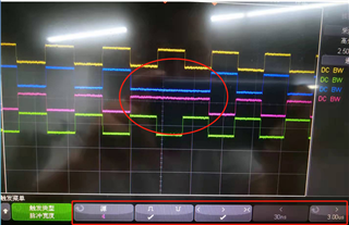
下面时问题波形:
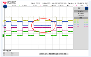
请帮我验证一下,谢谢。