

手上有连块280023C芯片板子,一块80PIN脚,一块64PIN脚。把在80PIN芯片上调试好的程序烧到64PIN的芯片里面,can发送会有很多错误帧(CAN引脚是兼容的GPIO4、GPIO5)。
然后就使用例程can_ex1_loopback进行调试,如下过程:
1、配置好引脚、报文信息后,编译烧录。两块板子都能正常发送can报文,无错误帧。
2、将can_ex1_loopback.c中报文数据的赋值语句屏蔽,
// txMsgData[0] = 0x01;
// txMsgData[1] = 0x02;
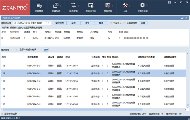
再测试,80PIN的板子正常发送,但是64PIN的板子会出现错误帧。无法理解屏蔽这两条语句对发送会有什么影响。
这和我再80PIN板子上调好的程序,再64Pin板子上有类似情况。
3、对比测试了两块板子芯片端和Can网络上的电压波形,波形的边沿上升下降时间及电平无明显差异。
board.c文件
#include "board.h"

void Board_init()
{
	EALLOW;

	PinMux_init();
	CAN_init();

	EDIS;
}

void PinMux_init()
{
	//CANA -> myCAN0 Pinmux
	GPIO_setPinConfig(GPIO_5_CANA_RX);
	GPIO_setPinConfig(GPIO_4_CANA_TX);

}

void CAN_init(){

    //myCAN0 initialization
    CAN_initModule(myCAN0_BASE);

    // Refer to the Driver Library User Guide for information on how to set
    // tighter timing control. Additionally, consult the device data sheet
    // for more information about the CAN module clocking.
    //
    CAN_setBitRate(myCAN0_BASE, DEVICE_SYSCLK_FREQ, 250000, 20);

    // Initialize the transmit message object used for sending CAN messages.
    // Message Object Parameters:
    //      Message Object ID Number: 1
    //      Message Identifier: 4660
    //      Message Frame: CAN_MSG_FRAME_STD
    //      Message Type: CAN_MSG_OBJ_TYPE_TX
    //      Message ID Mask: 0
    //      Message Object Flags:
    //      Message Data Length: 8 Bytes
    //
    CAN_setupMessageObject(myCAN0_BASE, 1, 4660, CAN_MSG_FRAME_STD,CAN_MSG_OBJ_TYPE_TX, 0, 0,8);
    // Initialize the transmit message object used for sending CAN messages.
    // Message Object Parameters:
    //      Message Object ID Number: 2
    //      Message Identifier: 4660
    //      Message Frame: CAN_MSG_FRAME_STD
    //      Message Type: CAN_MSG_OBJ_TYPE_RX
    //      Message ID Mask: 0
    //      Message Object Flags: CAN_MSG_OBJ_NO_FLAGS
    //      Message Data Length: 8 Bytes
    //
    CAN_setupMessageObject(myCAN0_BASE, 2, 4660, CAN_MSG_FRAME_STD,CAN_MSG_OBJ_TYPE_RX, 0, CAN_MSG_OBJ_NO_FLAGS,8);
}
can_ex1_loopback.c文件
#include "driverlib.h"
#include "device.h"
#include "board.h"

//
// Defines
//
#define MSG_DATA_LENGTH    8

//
// Globals
//
volatile unsigned long msgCount = 0;

//
// Main
//
void main(void)
{
    uint16_t txMsgData[8], rxMsgData[8];

    //
    // Initialize device clock and peripherals
    //
    Device_init();

    //
    // Initialize GPIO and configure GPIO pins for CANTX/CANRX
    //
    Device_initGPIO();

    //
    // Board initialization
    //
    Board_init();

    //
    // Initialize PIE and clear PIE registers. Disables CPU interrupts.
    //
    Interrupt_initModule();

    //
    // Initialize the PIE vector table with pointers to the shell Interrupt
    // Service Routines (ISR).
    //
    Interrupt_initVectorTable();

    //
    // Enable Global Interrupt (INTM) and realtime interrupt (DBGM)
    //
    EINT;
    ERTM;

    //
    // Start CAN module operations
    //
    CAN_startModule(myCAN0_BASE);

    //
    // Setup send and receive buffers
    //
//    txMsgData[0] = 0x01;
//    txMsgData[1] = 0x02;
    *(uint16_t *)rxMsgData = 0;

    //
    // Loop Forever - Send and Receive data continuously
    //
    for(;;)
    {
        //
        // Send CAN message data from message object 1
        //
        CAN_sendMessage(myCAN0_BASE, 1, MSG_DATA_LENGTH, txMsgData);

        //
        // Delay before receiving the data
        //
        DEVICE_DELAY_US(100000);

        //
        // Read CAN message object 2 and check for new data
        //
        if (CAN_readMessage(myCAN0_BASE, 2, rxMsgData))
        {
            //
            // Check that received data matches sent data.
            // Device will halt here during debug if data doesn't match.
            //
            if((txMsgData[0] != rxMsgData[0]) ||
               (txMsgData[1] != rxMsgData[1]))
            {
                //asm(" ESTOP0");
            }
            else
            {
                //
                // Increment message received counter
                //
                msgCount++;
            }
        }
        else
        {
            //
            // Device will halt here during debug if no new data was received.
            //
            //asm(" ESTOP0");
        }

        //
        // Increment the value in the transmitted message data.
        //
        //txMsgData[0] += 0x01;
        //txMsgData[1] += 0x01;

        //
        // Reset data if exceeds a byte
        //
        if(txMsgData[0] > 0xFF)
        {
            txMsgData[0] = 0;
        }
        if(txMsgData[1] > 0xFF)
        {
            txMsgData[1] = 0;
        }
    }
}

//
// End of File
//

