在这颗芯片的例程中,没有看到作为I2C从机的程序,我想要一个参考程序,满足以下要求:
1. 从机,8位数据。
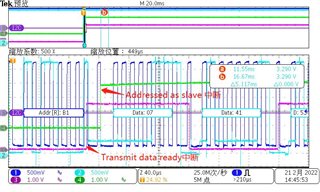
2. 能中断响应I2C。
3. 对主机而言,这颗芯片在收到地址后能进入中断,在接收和发送一个数据后,也能进入中断。
麻烦提供一个参考程序,谢谢!
在这颗芯片的例程中,没有看到作为I2C从机的程序,我想要一个参考程序,满足以下要求:
1. 从机,8位数据。
2. 能中断响应I2C。
3. 对主机而言,这颗芯片在收到地址后能进入中断,在接收和发送一个数据后,也能进入中断。
麻烦提供一个参考程序,谢谢!