

Other Parts Discussed in Thread: C2000WARE, TMS320F28379D
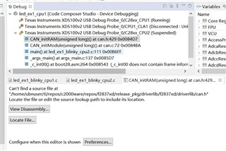
利用C2000ware中28379D的双核例程led_ex1_blinky_cpu1和led_ex1_blinky_cpu2烧录到开发板上,指示灯可以在CPU1和CPU2的控制下闪烁,之后根据C2000 ware中的单核例程中的can_ex4_simple_transmit中的can例程加入到双核点灯例程中,CAN的GPIO的定义以及CAN的主控选择语句在CPU1中,其他CAN的相应配置在CPU2中定义,在debug过程中CPU2进不去CAN的CAN_initModule(CANB_BASE),暂停CPU2的仿真,出现下面界面。
代码如下:
CPU1:
#include "driverlib.h"
#include "device.h"
#include "inc/hw_ipc.h"

void main(void)
{
    uint16_t ipcFlag17 = 17U;

    Device_init();
    Device_initGPIO();


    SysCtl_selectCPUForPeripheral(SYSCTL_CPUSEL8_CAN, 2, SYSCTL_CPUSEL_CPU2);

#ifdef _STANDALONE
#ifdef _FLASH
    //
    // Send boot command to allow the CPU2 application to begin execution
    //
    Device_bootCPU2(C1C2_BROM_BOOTMODE_BOOT_FROM_FLASH);
#else
    //
    // Send boot command to allow the CPU2 application to begin execution
    //
    Device_bootCPU2(C1C2_BROM_BOOTMODE_BOOT_FROM_RAM);

#endif // _FLASH
#endif // _STANDALONE

    //
    // Initialize GPIO and configure the GPIO pin as a push-pull output
    //


    GPIO_setPinConfig(GPIO_12_CANTXB);
    GPIO_setPinConfig(GPIO_17_CANRXB);

    GPIO_setPadConfig(DEVICE_GPIO_PIN_LED1, GPIO_PIN_TYPE_STD);
    GPIO_setDirectionMode(DEVICE_GPIO_PIN_LED1, GPIO_DIR_MODE_OUT);
    GPIO_setPadConfig(DEVICE_GPIO_PIN_LED2, GPIO_PIN_TYPE_STD);
    GPIO_setDirectionMode(DEVICE_GPIO_PIN_LED2, GPIO_DIR_MODE_OUT);

    //
    // Configure CPU2 to control the LED GPIO
    //

    GPIO_setMasterCore(DEVICE_GPIO_PIN_LED2, GPIO_CORE_CPU2);


    HWREG(IPC_BASE + IPC_O_SET) = 1UL << ipcFlag17;
    //
    // Initialize PIE and clear PIE registers. Disables CPU interrupts.
    //
    Interrupt_initModule();
    //
    // Initialize the PIE vector table with pointers to the shell Interrupt
    // Service Routines (ISR).
    //
    Interrupt_initVectorTable();
    //
    // Enable Global Interrupt (INTM) and realtime interrupt (DBGM)
    //
    EINT;
    ERTM;
    //
    // Loop Forever
    //
    for(;;)
    {
        GPIO_writePin(DEVICE_GPIO_PIN_LED1, 0);
        DEVICE_DELAY_US(500000);
        GPIO_writePin(DEVICE_GPIO_PIN_LED1, 1);
        DEVICE_DELAY_US(500000);

    }
}
CPU2:
#include "driverlib.h"
#include "device.h"
#include "inc/hw_ipc.h"

//
// Main
//

#define TXCOUNT  100000
#define MSG_DATA_LENGTH    8
#define TX_MSG_OBJ_ID      1


#pragma DATA_SECTION(txMsgData, "SHARERAMGS2");
uint16_t txMsgData[8];


void main(void)
{


    uint16_t ipcFlag17 = 17U;

    Interrupt_initModule();

    //
    // Initialize the PIE vector table with pointers to the shell Interrupt
    // Service Routines (ISR).
    //
    Interrupt_initVectorTable();

    while(!(HWREG(IPC_BASE + IPC_O_STS) & (1UL << ipcFlag17)))
                  {
                  }

    //
    // ACK IPC flag 17 for CPU1
    //
    HWREG(IPC_BASE + IPC_O_ACK) = 1UL << ipcFlag17;


   CAN_initModule(CANB_BASE);
   //
   // Set up the CAN bus bit rate to 500kHz for each module
   // Refer to the Driver Library User Guide for information on how to set
   // tighter timing control. Additionally, consult the device data sheet
   // for more information about the CAN module clocking.
   //
     CAN_setBitRate(CANB_BASE, 200000000, 500000, 20);

     //
     // Initialize the transmit message object used for sending CAN messages.
     // Message Object Parameters:
     //      CAN Module: A
     //      Message Object ID Number: 1
     //      Message Identifier: 0x95555555
     //      Message Frame: Extended
     //      Message Type: Transmit
     //      Message ID Mask: 0x0
     //      Message Object Flags: None
     //      Message Data Length: 4 Bytes
     //
     CAN_setupMessageObject(CANB_BASE, TX_MSG_OBJ_ID, 0x1,
                                   CAN_MSG_FRAME_STD, CAN_MSG_OBJ_TYPE_TX, 1,
                                   CAN_MSG_OBJ_NO_FLAGS, MSG_DATA_LENGTH);


     // Initialize the transmit message object data buffer to be sent
     //
     txMsgData[0] = 0x01;
     txMsgData[1] = 0x23;
     txMsgData[2] = 0x45;
     txMsgData[3] = 0x67;
     txMsgData[4] = 0x89;
     txMsgData[5] = 0xAB;
     txMsgData[6] = 0xCD;
     txMsgData[7] = 0xEF;

     //
     // Start CAN module A operations
     //
     CAN_startModule(CANB_BASE);
    //
    // Enable Global Interrupt (INTM) and realtime interrupt (DBGM)
    //
    EINT;
    ERTM;

    //
    // Loop Forever
    //
    for(;;)
    {
        GPIO_writePin(DEVICE_GPIO_PIN_LED2, 0);
        DEVICE_DELAY_US(500000);
        GPIO_writePin(DEVICE_GPIO_PIN_LED2, 1);
        DEVICE_DELAY_US(500000);
       CAN_sendMessage(CANB_BASE, TX_MSG_OBJ_ID, MSG_DATA_LENGTH, txMsgData);
    }
}

