This thread has been locked.

If you have a related question, please click the "Ask a related question" button in the top right corner. The newly created question will be automatically linked to this question.

TMS320F280025C: 官方捕获例程无法计算占空比

Part Number: TMS320F280025C
Other Parts Discussed in Thread: C2000WARE

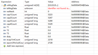
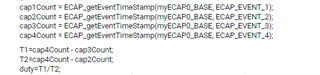
我使用了C:\ti\c2000\C2000Ware_4_00_00_00\driverlib\f28002x\examples\ecap\ecap_ex2_capture_pwm例程进行测试,但是发现捕获到的数据,在debug时cap1,cap2,cap3,cap4的值不一样,可是做差后数值一样,因此无法算占空比。然后设置断点,发现每次捕获到的数是一样的,不知道问题出在哪里

  • 你好,你是用的原始工程做的测试吗?也就是说在没有对例程做修改的情况下做的测试?

    在debug时cap1,cap2,cap3,cap4的值不一样,可是做差后数值一样

    这段是什么意思?例程应该是只使用了eCAP1啊。

  • //
    // Included Files
    //
    #include "driverlib.h"
    #include "device.h"
    #include "board.h"
    
    //
    // Defines
    //
    #define PWM3_TIMER_MIN 500U
    #define PWM3_TIMER_MAX 8000U
    #define EPWM_TIMER_UP 1U
    #define EPWM_TIMER_DOWN 0U
    
    //
    // Globals
    //
    uint32_t ecap1IntCount;
    uint32_t ecap1PassCount;
    uint32_t epwm3TimerDirection;
    volatile uint32_t cap1Count;
    volatile uint32_t cap2Count;
    volatile uint32_t cap3Count;
    volatile uint32_t cap4Count;
    volatile uint32_t epwm3PeriodCount;
    
    
    //
    // Function Prototypes
    //
    void error(void);
    void initECAP(void);
    void initEPWM(void);
    
    volatile float T1=0,T2=0,T3=0;
    volatile float frequence=0;
    volatile float duty=0;


    //
    // Comment to Make the CAN Controller work as a Receiver.
    //
    
    #define TX_MSG_OBJ_ID 20
    //#else
    
    
    #define RX_CMD_OBJ_ID 1
    
    volatile uint32_t INT_OBJ_ID = 0;
    
    //#define RX_MSG_OBJ_RESERVED1 2
    //#define RX_MSG_OBJ_CMD 3
    //#define RX_MSG_OBJ_DATA 4
    //#define RX_MSG_OBJ_RESERVED2 5
    //#define RX_MSG_OBJ_RESERVED3 6
    //#define RX_MSG_OBJ_RESERVED4 7
    //#define RX_MSG_OBJ_RESERVED5 8
    //#define RX_MSG_OBJ_REMOTE 11
    
    #define RX_DATA_LENGTH 8
    #define TX_DATA_LENGTH 8
    #define MSGCOUNT 10


    //
    // Globals
    //


    volatile uint32_t txMsgCount = 0;
    volatile uint32_t txMsgSuccessful = 1;
    
    uint16_t textdata[32];
    
    //volatile unsigned long i;


    uint16_t txMsgData[32];
    uint16_t rxMsgData[32];


    volatile uint32_t rxMsgCount = MSGCOUNT,rxcount=0;
    
    
    uint16_t ER_CMD[32]={'E','R','R', '_','C','M','D'};//
    uint16_t CO_CMD[32]={'C','O','R', 'R','E','C','T','_','D','A','T','A'};//
    
    
    volatile uint32_t errorFlag = 0,error_log=0;
    volatile int waittask=0;
    //
    // Function Prototypes
    //
    __interrupt void canaISR(void);
    
    //
    // Main
    //
    void main(void)
    {
    // int waittask=0;
    
    
    //
    // Initialize device clock and peripherals
    //
    Device_init();
    
    //
    // Disable pin locks and enable internal pullups.
    //
    Device_initGPIO();
    
    //
    // Initialize PIE and clear PIE registers. Disables CPU interrupts.
    //
    Interrupt_initModule();
    
    //
    // Initialize the PIE vector table with pointers to the shell Interrupt
    // Service Routines (ISR).
    //
    Interrupt_initVectorTable();
    
    //
    // Configure GPIO4/5 as ePWM3A/3B
    //
    GPIO_setPadConfig(4,GPIO_PIN_TYPE_STD);
    GPIO_setPinConfig(GPIO_4_EPWM3_A);
    GPIO_setPadConfig(5,GPIO_PIN_TYPE_STD);
    GPIO_setPinConfig(GPIO_5_EPWM3_B);
    
    //
    // Board initialization
    // Configure GPIO 16 as eCAP input
    // Enable interrupts required for this example
    //
    Board_init();
    
    //
    // Configure ePWM
    //
    initEPWM();
    
    //
    // Initialize counters:
    //
    ecap1IntCount = 0U;
    ecap1PassCount = 0U;
    epwm3PeriodCount = 0U;
    cap1Count = 0U;
    cap2Count = 0U;
    cap3Count = 0U;
    cap4Count = 0U;
    
    //
    // Enable Global Interrupt (INTM) and Real time interrupt (DBGM)
    //
    EINT;
    ERTM;


    // Loop forever. Suspend or place breakpoints to observe the buffers.
    
    for(;;)
    {
    
    NOP;
    }
    }
    
    //
    // initEPWM - Configure ePWM
    //
    void initEPWM()
    {
    //
    // Disable sync(Freeze clock to PWM as well)
    //
    SysCtl_disablePeripheral(SYSCTL_PERIPH_CLK_TBCLKSYNC);
    
    //
    // Configure ePWM
    // Counter runs in up-count mode.
    // Action qualifier will toggle output on period match
    
    EPWM_setTimeBaseCounterMode(EPWM3_BASE, EPWM_COUNTER_MODE_UP);
    //TBPRD
    EPWM_setTimeBasePeriod(EPWM3_BASE, PWM3_TIMER_MIN);
    //TBPH
    EPWM_setPhaseShift(EPWM3_BASE, 25010U);
    
    EPWM_setActionQualifierAction(EPWM3_BASE,
    EPWM_AQ_OUTPUT_A,
    EPWM_AQ_OUTPUT_TOGGLE,
    EPWM_AQ_OUTPUT_ON_TIMEBASE_PERIOD);
    
    // TBCLK = EPWMCLK/(highSpeedPrescaler * pre-scaler)
    // EPWM_setClockPrescaler(uint32_t base, EPWM_ClockDivider prescaler,
    // EPWM_HSClockDivider highSpeedPrescaler)
    EPWM_setClockPrescaler(EPWM3_BASE,
    EPWM_CLOCK_DIVIDER_1,
    EPWM_HSCLOCK_DIVIDER_2);//EPWM_HSCLOCK_DIVIDER_2
    
    epwm3TimerDirection = EPWM_TIMER_UP;
    
    //
    // Enable sync and clock to PWM
    //
    SysCtl_enablePeripheral(SYSCTL_PERIPH_CLK_TBCLKSYNC);
    }
    
    //
    // myECAP0 ISR
    //
    __interrupt void INT_myECAP1_ISR(void)
    {
    //
    // Get the capture counts. Each capture should be 2x the ePWM count
    // because of the ePWM clock divider.
    //
    cap1Count = ECAP_getEventTimeStamp(myECAP0_BASE, ECAP_EVENT_1);
    cap2Count = ECAP_getEventTimeStamp(myECAP0_BASE, ECAP_EVENT_2);
    cap3Count = ECAP_getEventTimeStamp(myECAP0_BASE, ECAP_EVENT_3);
    cap4Count = ECAP_getEventTimeStamp(myECAP0_BASE, ECAP_EVENT_4);
    
    T1=cap4Count - cap3Count;
    T2=cap4Count - cap2Count;
    duty=T1/T2;
    // T1=ECAP_getEventTimeStamp(myECAP0_BASE, ECAP_EVENT_2) - cap1Count;
    // T2=ECAP_getEventTimeStamp(myECAP0_BASE, ECAP_EVENT_3) - cap1Count;
    
    
    //
    // Compare the period value with the captured count
    //
    epwm3PeriodCount = EPWM_getTimeBasePeriod(EPWM3_BASE);


    if(cap2Count > ((epwm3PeriodCount *2) + 2U) ||
    cap2Count < ((epwm3PeriodCount *2) - 2U))
    {
    error();
    }
    
    if(cap3Count > ((epwm3PeriodCount *2) + 2U) ||
    cap3Count < ((epwm3PeriodCount *2) - 2U))
    {
    error();
    }
    
    if(cap4Count > ((epwm3PeriodCount *2) + 2U) ||
    cap4Count < ((epwm3PeriodCount *2) - 2U))
    {
    error();
    }
    
    ecap1IntCount++;
    
    //
    // Keep track of the ePWM direction and adjust period accordingly to
    // generate a variable frequency PWM.
    
    if(epwm3TimerDirection == EPWM_TIMER_UP)
    {
    if(epwm3PeriodCount < PWM3_TIMER_MAX)
    {
    EPWM_setTimeBasePeriod(EPWM3_BASE, ++epwm3PeriodCount);
    
    }
    else
    {
    epwm3TimerDirection = EPWM_TIMER_DOWN;
    EPWM_setTimeBasePeriod(EPWM3_BASE, ++epwm3PeriodCount);
    
    }
    }
    else
    {
    if(epwm3PeriodCount > PWM3_TIMER_MIN)
    {
    EPWM_setTimeBasePeriod(EPWM3_BASE, --epwm3PeriodCount);
    
    }
    else
    {
    epwm3TimerDirection = EPWM_TIMER_UP;
    EPWM_setTimeBasePeriod(EPWM3_BASE, ++epwm3PeriodCount);
    
    }
    }
    
    //
    // Count correct captures
    //
    ecap1PassCount++;
    
    //
    // Clear interrupt flags for more interrupts.
    //
    ECAP_clearInterrupt(myECAP0_BASE,ECAP_ISR_SOURCE_CAPTURE_EVENT_4);
    ECAP_clearGlobalInterrupt(myECAP0_BASE);
    
    //
    // Start eCAP
    //s
    ECAP_reArm(myECAP0_BASE);
    
    //
    // Acknowledge the group interrupt for more interrupts.
    //
    Interrupt_clearACKGroup(INT_myECAP0_INTERRUPT_ACK_GROUP);
    }
    
    //
    // CAN A ISR - The interrupt service routine called when a CAN interrupt is
    // triggered on CAN module A.
    //
    __interrupt void
    canaISR(void)
    {
    uint32_t status;
    
    //
    // Read the CAN-B interrupt status to find the cause of the interrupt
    //
    status = CAN_getInterruptCause(CANA_BASE);
    
    //
    // If the cause is a controller status interrupt, then get the status
    //
    if(status == CAN_INT_INT0ID_STATUS)
    {
    //
    // Read the controller status. This will return a field of status
    // error bits that can indicate various errors. Error processing
    // is not done in this example for simplicity. Refer to the
    // API documentation for details about the error status bits.
    // The act of reading this status will clear the interrupt.
    //
    status = CAN_getStatus(CANA_BASE);
    
    //
    // Check to see if an error occurred.
    //
    if
    (
    ((status & ~(CAN_STATUS_RXOK|CAN_STATUS_TXOK)) != CAN_STATUS_LEC_MSK) &&
    ((status & ~(CAN_STATUS_RXOK|CAN_STATUS_TXOK)) != CAN_STATUS_LEC_NONE)
    )
    {
    
    //
    // Set a flag to indicate some errors may have occurred.
    //
    error_log = status;
    // errorFlag = 1;
    ESTOP0;
    
    }
    }
    else if(status == TX_MSG_OBJ_ID)
    {
    // GPIO_writePin(31, 0);
    //
    // Getting to this point means that the TX interrupt occurred on
    // message object 1, and the message TX is complete. Clear the
    // message object interrupt.
    //
    
    // GPIO_writePin(31, 0);
    CAN_clearInterruptStatus(CANA_BASE, TX_MSG_OBJ_ID);
    
    //
    // Increment a counter to keep track of how many messages have been
    // transmitted. In a real application this could be used to set flags to
    // indicate when a message is transmitted.
    //
    txMsgCount++;
    
    //
    // Since the message was transmitted, clear any error flags.
    //
    errorFlag = 0;
    
    //
    // Clear the message transmitted successful Flag.
    //
    txMsgSuccessful = 0;
    // GPIO_writePin(31, 1);
    }
    
    else if(status == RX_CMD_OBJ_ID)
    {
    
    CAN_readMessage(CANA_BASE, RX_CMD_OBJ_ID, rxMsgData);
    // CAN_sendMessage(CANA_BASE, TX_MSG_OBJ_ID,TX_DATA_LENGTH,CO_CMD);
    CAN_clearInterruptStatus(CANA_BASE, RX_CMD_OBJ_ID);


    INT_OBJ_ID = RX_CMD_OBJ_ID;
    waittask++;
    
    rxMsgCount--;
    rxcount++;
    errorFlag = 0;
    
    }
    // else if(status == RX_MSG_OBJ_DATA)
    // {
    //
    // CAN_readMessage(CANA_BASE, RX_MSG_OBJ_DATA, rxMsgData12);
    //
    // CAN_clearInterruptStatus(CANA_BASE, RX_MSG_OBJ_DATA);
    //
    // rxMsgCount--;
    //
    // errorFlag = 0;
    // }
    //
    //
    // else if(status == RX_MSG_OBJ_REMOTE)
    // {
    // CAN_readMessage(CANA_BASE, RX_MSG_OBJ_REMOTE, rxMsgData13);
    // CAN_clearInterruptStatus(CANA_BASE, RX_MSG_OBJ_REMOTE);
    //
    // rxMsgCount--;
    //
    // errorFlag = 0;
    //
    // }
    
    //#endif
    //
    // If something unexpected caused the interrupt, this would handle it.
    //
    else
    {
    //
    // Spurious interrupt handling can go here.
    //
    }
    // GPIO_writePin(31, 1);
    //
    // Clear the global interrupt flag for the CAN interrupt line
    //
    CAN_clearGlobalInterruptStatus(CANA_BASE, CAN_GLOBAL_INT_CANINT0);
    
    //
    // Acknowledge this interrupt located in group 9
    //
    Interrupt_clearACKGroup(INTERRUPT_ACK_GROUP9);
    }
    
    //
    // error - Error function
    //
    void error()
    {
    ESTOP0;
    }

  • 这个是debug时的结果

  • 您好,如果方便的话能不能帮我看下哪里有问题?感谢

  • 额,我是在看,但是你发这么一大段代码上来,也不对代码做些什么说明/标注,我看起来很慢也很累啊

  • 不好意思啊,我的问题。我只是在例程的基础上增加了这个

    但是得到的结果是捕获值相同

  • 额,不好意思我一开始没看懂你的编程逻辑。

    目前来看你的程序应该就是把cap2Count、cap3Count、cap4Count的值拉出来做了一个计算,没在其他地方做其他配置方面的修改?

    怀疑是否跟你的数据类型定义有关。我会测试一下你的程序之后确认一下问题在哪里。

  • 是的,因为之前测试CAN 的功能,没有全部删除,有点乱 。现在的问题是cap2Count、cap3Count、cap4Count的值是一样的。

  • 你好,请问你的问题是解决了吗?

    其实我一直没明白你说的“cap2Count、cap3Count、cap4Count的值是一样的”是什么意思?因为正常情况下这三个值就是应该是一样,或者差几个值(看运行的电位不同)。

  • 这四个不是分别捕获的上升沿,下降沿时计数器的值吗?为什么会是一样的啊?现在这个问题解决了。

  • 你好,这个似乎跟之前的例程不同,里面的值是捕获的次数而不是计数器的值。

    我会再看一下之后回复你。

  • 看了一下,因为程序里面对ECCTL1.bit.CTRRST1设置的是1,Counter Reset on Capture Event 1