Part Number: TMS320F28388D
Other Parts Discussed in Thread: C2000WARE,
背景:CCS软件为12.0版本、C2000Ware_4_01_00_00、新买的TMS320F28388D开发板和XDS110仿真器
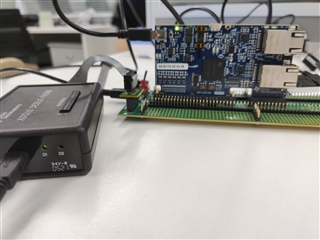
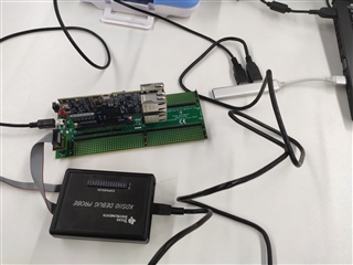
问题:根据开发板手册完成接线后,通过CCS打开例程进行测试仿真器是否接上时,出现错误。
另外在仿真器连接测试期间XDS110的D2灯亮红色并闪烁
希望能告知解决方法和查找问题的测试方法,谢谢!
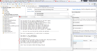
连接报错信息:
The explanation is:
The JTAG IR and DR scan-paths cannot circulate bits, they may be broken.
An attempt to scan the JTAG scan-path has failed.
The target's JTAG scan-path appears to be broken
with a stuck-at-ones or stuck-at-zero fault.
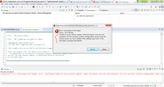
Debug报错
Error connecting to the target: (Error -2131 @ 0x0)
Unable to access device register. Reset the device, and retry the operation. If error persists, confirm configuration, power-cycle the board, and/or try more reliable JTAG settings (e.g. lower TCLK).
(Emulation package 9.8.0.00235)
连接测试和Debug报错图片:
接线实物图片: