

Part Number: TMS320F28027
#pragma DATA_SECTION (Spwm_Vo_Val1,"scidata");
uint16_t print_cnt = 0;
int16 Spwm_Vo_Val1[400]={0};
printf("\r\nLI %d",Spwm_Vo_Val1[print_cnt]);
print_cnt=(print_cnt+1)%400;
打印的数据始终不变实际上不把Spwm_Vo_Val1定向在scidata段打印的数据就是变化的
打印结果为 LI 1
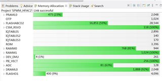
CMD文件和编译后的各自占用的内存会以文件形式上传
/*
// TI File $Revision: /main/7 $
// Checkin $Date: July 6, 2009   17:25:36 $
//###########################################################################
//
// FILE:	F28027.cmd
//
// TITLE:	Linker Command File For F28027 Device
//
//###########################################################################
// $TI Release: 2802x C/C++ Header Files and Peripheral Examples V1.29 $
// $Release Date: January 11, 2011 $
//###########################################################################
*/

/* ======================================================
// For Code Composer Studio V2.2 and later
// ---------------------------------------
// In addition to this memory linker command file,
// add the header linker command file directly to the project.
// The header linker command file is required to link the
// peripheral structures to the proper locations within
// the memory map.
//
// The header linker files are found in <base>\DSP2802_Headers\cmd
//
// For BIOS applications add:      DSP2802x_Headers_BIOS.cmd
// For nonBIOS applications add:   DSP2802x_Headers_nonBIOS.cmd
========================================================= */

/* ======================================================
// For Code Composer Studio prior to V2.2
// --------------------------------------
// 1) Use one of the following -l statements to include the
// header linker command file in the project. The header linker
// file is required to link the peripheral structures to the proper
// locations within the memory map                                    */

/* Uncomment this line to include file only for non-BIOS applications */
/* -l DSP2802x_Headers_nonBIOS.cmd */

/* Uncomment this line to include file only for BIOS applications */
/* -l DSP2802x_Headers_BIOS.cmd */

/* 2) In your project add the path to <base>\DSP2802x_headers\cmd to the
   library search path under project->build options, linker tab,
   library search path (-i).
/*========================================================= */

/* Define the memory block start/length for the F28027
   PAGE 0 will be used to organize program sections
   PAGE 1 will be used to organize data sections

   Notes:
         Memory blocks on F2802x are uniform (ie same
         physical memory) in both PAGE 0 and PAGE 1.
         That is the same memory region should not be
         defined for both PAGE 0 and PAGE 1.
         Doing so will result in corruption of program
         and/or data.

         The L0 memory block is mirrored - that is
         it can be accessed in high memory or low memory.
         For simplicity only one instance is used in this
         linker file.

         Contiguous SARAM memory blocks or flash sectors can be
         be combined if required to create a larger memory block.

         FLASHD      : origin = 0x3F0000, length = 0x002000
         FLASHC      : origin = 0x3F2000, length = 0x002000
         FLASHB      : origin = 0x3F4000, length = 0x002000
*/

MEMORY
{
PAGE 0:    /* Program Memory */
           /* Memory (RAM/FLASH/OTP) blocks can be moved to PAGE1 for data allocation */

   PRAML0      : origin = 0x008000, length = 0x000800     /* on-chip RAM block L0 */
   OTP         : origin = 0x3D7800, length = 0x000400     /* on-chip OTP */
   FLASHABCD2  : origin = 0x3F1000, length = 0x006F80     /* on-chip FLASH */
   CSM_RSVD    : origin = 0x3F7F80, length = 0x000076     /* Part of FLASHA.  Program with all 0x0000 when CSM is in use. */
   BEGIN       : origin = 0x3F7FF6, length = 0x000002     /* Part of FLASHA.  Used for "boot to Flash" bootloader mode. */
   CSM_PWL_P0  : origin = 0x3F7FF8, length = 0x000008     /* Part of FLASHA.  CSM password locations in FLASHA */

   IQTABLES    : origin = 0x3FE000, length = 0x000B50     /* IQ Math Tables in Boot ROM */
   IQTABLES2   : origin = 0x3FEB50, length = 0x00008C     /* IQ Math Tables in Boot ROM */
   IQTABLES3   : origin = 0x3FEBDC, length = 0x0000AA	  /* IQ Math Tables in Boot ROM */

   ROM         : origin = 0x3FF27C, length = 0x000D44     /* Boot ROM */
   RESET       : origin = 0x3FFFC0, length = 0x000002     /* part of boot ROM  */
   VECTORS     : origin = 0x3FFFC2, length = 0x00003E     /* part of boot ROM  */

PAGE 1 :   /* Data Memory */
           /* Memory (RAM/FLASH/OTP) blocks can be moved to PAGE0 for program allocation */
           /* Registers remain on PAGE1                                                  */

   BOOT_RSVD   : origin = 0x000000, length = 0x000050     /* Part of M0, BOOT rom will use this for stack */
   RAMM0       : origin = 0x000050, length = 0x0003B0     /* on-chip RAM block M0 */
   RAMM1       : origin = 0x000400, length = 0x000400     /* on-chip RAM block M1 */
   DRAML0      : origin = 0x008800, length = 0x000800     /* on-chip RAM block L0 */
   FLASHD1     : origin = 0x3F0000, length = 0x001000
}

/* Allocate sections to memory blocks.
   Note:
         codestart user defined section in DSP28_CodeStartBranch.asm used to redirect code
                   execution when booting to flash
         ramfuncs  user defined section to store functions that will be copied from Flash into RAM
*/

SECTIONS
{

   /* Allocate program areas: */
   .cinit              : > FLASHABCD2       PAGE = 0
   .pinit              : > FLASHABCD2,      PAGE = 0
   .text               : > FLASHABCD2       PAGE = 0
   codestart           : > BEGIN        PAGE = 0
   ramfuncs            : LOAD = FLASHABCD2,
                         RUN = PRAML0,
                         LOAD_START(_RamfuncsLoadStart),
                         LOAD_END(_RamfuncsLoadEnd),
                         RUN_START(_RamfuncsRunStart),
                         PAGE = 0

   csmpasswds          : > CSM_PWL_P0   PAGE = 0
   csm_rsvd            : > CSM_RSVD     PAGE = 0

   /* Allocate uninitalized data sections: */
   .stack              : > RAMM0        PAGE = 1
   .ebss               : > DRAML0       PAGE = 1
   .esysmem            : > RAMM1 |DRAML0       PAGE = 1
//   .cio                : > DRAML0    PAGE = 1// //.cio    �����HFUPS�ļ���ͷ            : >> RAMM1 | DRAML0 |  DRAMLL0     PAGE = 1//    .cio                : >> RAMM0 | RAMM1 | DRAML0       PAGE = 1
//   scidata             : > FLASHD1    PAGE = 1
   /* Initalized sections go in Flash */
   /* For SDFlash to program these, they must be allocated to page 0 */
   .econst             : > FLASHABCD2       PAGE = 0
   .switch             : > FLASHABCD2       PAGE = 0

   /* Allocate IQ math areas: */
   IQmath              : > FLASHABCD2       PAGE = 0            /* Math Code */
   IQmathTables        : > IQTABLES,    	PAGE = 0, TYPE = NOLOAD

   /* Uncomment the section below if calling the IQNexp() or IQexp()
      functions from the IQMath.lib library in order to utilize the
      relevant IQ Math table in Boot ROM (This saves space and Boot ROM
      is 1 wait-state). If this section is not uncommented, IQmathTables2
      will be loaded into other memory (SARAM, Flash, etc.) and will take
      up space, but 0 wait-state is possible.
   */
   /*
   IQmathTables2    : > IQTABLES2, PAGE = 0, TYPE = NOLOAD
   {

              IQmath.lib<IQNexpTable.obj> (IQmathTablesRam)

   }
   */
   /* Uncomment the section below if calling the IQNasin() or IQasin()
      functions from the IQMath.lib library in order to utilize the
      relevant IQ Math table in Boot ROM (This saves space and Boot ROM
      is 1 wait-state). If this section is not uncommented, IQmathTables2
      will be loaded into other memory (SARAM, Flash, etc.) and will take
      up space, but 0 wait-state is possible.
   */
   /*
   IQmathTables3    : > IQTABLES3, PAGE = 0, TYPE = NOLOAD
   {

              IQmath.lib<IQNasinTable.obj> (IQmathTablesRam)

   }
   */

   /* .reset is a standard section used by the compiler.  It contains the */
   /* the address of the start of _c_int00 for C Code.   /*
   /* When using the boot ROM this section and the CPU vector */
   /* table is not needed.  Thus the default type is set here to  */
   /* DSECT  */
   .reset              : > RESET,      PAGE = 0, TYPE = DSECT
   vectors             : > VECTORS     PAGE = 0, TYPE = DSECT

}

/*
//===========================================================================
// End of file.
//===========================================================================
*/
谢谢!

