This thread has been locked.
If you have a related question, please click the "Ask a related question" button in the top right corner. The newly created question will be automatically linked to this question.
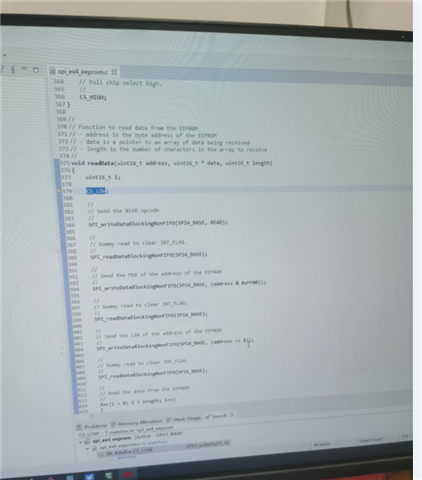
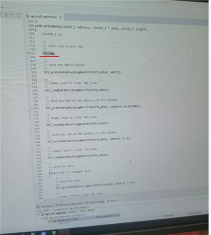
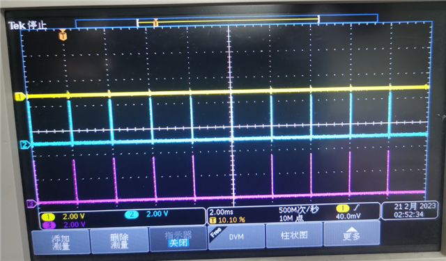
We want that TI DSP to communicate with A3 MCU through SPI interface.However, it was found that the function of enabling pin STE to automatically set high and set low could not be realized through DSP configuration.The DEMO source provided by FAE is also implemented through IO port simulation.As shown in the figures below, SPI read/write enable signal STE is also realized through IO simulation.
Hi,
I post this issue to the relevant engineer. I will reply you once I got response. Thanks for your patience.
Hi,
The example code you are pointing to uses SPISTE pin as GPIO output pin instead of SPI pin. That is the reason why they use CS_LOW (to bring chip select pin low) and CS_HIGH (to pull chip select pin high). It is not necessary to configure SPISTE pin as GPIO output pin. You can configure them as SPISTE pin itself. This give the SPI HW control over SPISTE pin and SPISTE pin is automatically pulled low to start SPI transaction and pulled high when SPI transaction needs to be ended.
This would however require you to change the pinmux selection.