

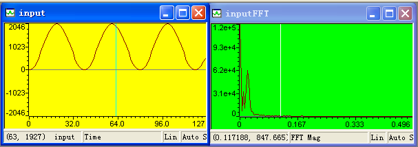
输入的input[N]图形如下,inputFFT为FFT Magnitude下的图形: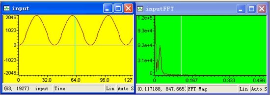
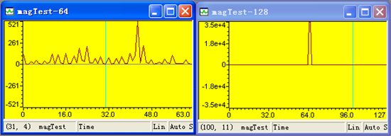
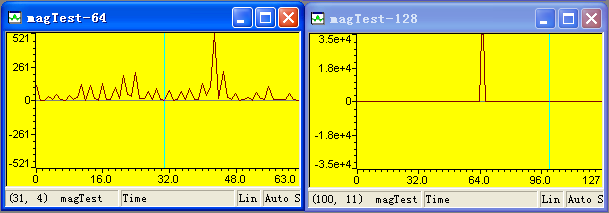
下图为magTest[ ]的64点与128点时图形,个人感觉不对,应该要同inputFFT一样才对啊,是不是哪里配错了:
源码如下:
#include "DSP28x_Project.h"     // Device Headerfile and Examples Include File
#include <fft.h>
#include"math.h"

// Prototype statements for functions found within this file.
interrupt void adc_isr(void);
void Adc_Config(void);


// Global variables used in this example:
Uint16 LoopCount;
#if 0
Uint16 ConversionCount;
Uint16 Voltage1[10];
Uint16 Voltage2[10];
#endif

#define PI 3.1415926
#define     N   128
long ipcb[N+2];
long mag[N/2+1];
long magTest[N/2+1];
#pragma DATA_SECTION(ipcb, "FFTipcb");
#pragma DATA_SECTION(mag, "FFTmag");

RFFT32  fft=RFFT32_128P_DEFAULTS;

RFFT32_ACQ  acq=FFTRACQ_DEFAULTS;


#if 1
unsigned int input[N]=
{

	0x000,0x00b,0x02c,0x062,0x0ac,0x109,0x176,0x1f1,0x307,0x39b,
	0x432,0x4c7,0x558,0x5e2,0x661,0x6d4,0x736,0x787,0x7c4,0x7ec,
	0x7fe,0x7ec,0x7c4,0x787,0x736,0x6d4,0x661,0x5e2,0x558,0x4c7,
	0x432,0x39b,0x307,0x1f1,0x176,0x109,0x0ac,0x062,0x02c,0x00b,

	0x000,0x00b,0x02c,0x062,0x0ac,0x109,0x176,0x1f1,0x307,0x39b,
	0x432,0x4c7,0x558,0x5e2,0x661,0x6d4,0x736,0x787,0x7c4,0x7ec,
	0x7fe,0x7ec,0x7c4,0x787,0x736,0x6d4,0x661,0x5e2,0x558,0x4c7,
	0x432,0x39b,0x307,0x1f1,0x176,0x109,0x0ac,0x062,0x02c,0x00b,

	0x000,0x00b,0x02c,0x062,0x0ac,0x109,0x176,0x1f1,0x307,0x39b,
	0x432,0x4c7,0x558,0x5e2,0x661,0x6d4,0x736,0x787,0x7c4,0x7ec,
	0x7fe,0x7ec,0x7c4,0x787,0x736,0x6d4,0x661,0x5e2,0x558,0x4c7,
	0x432,0x39b,0x307,0x1f1,0x176,0x109,0x0ac,0x062,0x02c,0x00b,

	0x000,0x00b,0x02c,0x062,0x0ac,0x109,0x176,0x1f1

};
#endif

main()
{
	int i;
	unsigned int *pInput;
	pInput=input;

// Step 1. Initialize System Control:
// PLL, WatchDog, enable Peripheral Clocks
// This example function is found in the DSP2803x_SysCtrl.c file.
   InitSysCtrl();


// Step 2. Initialize GPIO:
// This example function is found in the DSP2802x_Gpio.c file and
// illustrates how to set the GPIO to it's default state.
// InitGpio();  // Skipped for this example

// Step 3. Clear all interrupts and initialize PIE vector table:
// Disable CPU interrupts
   DINT;

// Initialize the PIE control registers to their default state.
// The default state is all PIE interrupts disabled and flags
// are cleared.
// This function is found in the DSP2802x_PieCtrl.c file.
   InitPieCtrl();

/* Initialize acquisition module                    */
        acq.buffptr=ipcb;
        acq.tempptr=ipcb;
        acq.size=N;
        acq.count=N;
        acq.acqflag=1;

/* Initialize FFT module                            */
        fft.ipcbptr=ipcb;
        fft.magptr=mag;
       // fft.winptr=(long *)win;
        fft.init(&fft);


// Disable CPU interrupts and clear all CPU interrupt flags:
   IER = 0x0000;
   IFR = 0x0000;
// This function is found in DSP2802x_PieVect.c.
   InitPieVectTable();

   for(;;)
   {
      LoopCount++;
        for(i=0;i<N;i++)
        {
 acq.input=((unsigned long)pInput[i])<<16; acq.update(&acq);
        }

        if (acq.acqflag==0)     // If the samples are acquired
        {
            fft.calc(&fft);
            fft.split(&fft);
            fft.mag(&fft);
            acq.acqflag=1;      // Enable the next acquisition

		for(i=0;i<N/2+1;i++)
		{

		   magTest[i]=sqrt(mag[i]);
		}
        }
   }

}