

Part Number: TMS320F28377D
Other Parts Discussed in Thread: SYSCONFIG
如题,我的CPU1代码为
#include "device.h"
#include "F28x_Project.h"
#include "board.h"
/**
* main.c
*/
void main(void)
{
Device_init(); // Initialize device clock and peripherals
Device_initGPIO(); // Initialize GPIO and configure the GPIO pin as a push-pull output
Interrupt_initModule(); // Initialize PIE and clear PIE registers. Disables CPU interrupts.
IER = 0x0000; //CPU级中断使能
IFR = 0x0000; //清除CPU级中断标志
Interrupt_initVectorTable(); // Initialize the PIE vector table with pointers to ISR
//IPC初始化
// Initialize SysConfig Settings
//
Board_init();
Device_bootCPU2(BOOT_MODE_CPU2);//启动CPU2
// Clear any IPC flags if set already
//
IPC_clearFlagLtoR(IPC_CPU1_L_CPU2_R, IPC_FLAG_ALL);
//
// Synchronize both the cores.
//
IPC_sync(IPC_CPU1_L_CPU2_R, CPU1_to_CPU2_IPC_FLAG31);
// IpcRegs.IPCSET.bit.IPC0=1;
EINT; // Enable Global Interrupt (INTM)
ERTM; // Enable real-time interrupt (DBGM)
for (;;)
{
IpcRegs.IPCSET.bit.IPC0=1;
DELAY_US(100000);
}
}
CPU2的工程为
#include "device.h"
#include "F28x_Project.h"
#include "board.h"
/**
* main.c
*/
void main(void)
{
//
// Initialize device clock and peripherals
//
Device_init();
//
// Initialize PIE and clear PIE registers. Disables CPU interrupts.
//
Interrupt_initModule();
//
// Initialize the PIE vector table with pointers to the shell Interrupt
// Service Routines (ISR).
//
Interrupt_initVectorTable();
//
// Initialize SysConfig Settings
//
Board_init();
//
// Clear any IPC flags if set already
//
IPC_clearFlagLtoR(IPC_CPU2_L_CPU1_R, IPC_FLAG_ALL);
//
// Enable Global Interrupt (INTM) and realtime interrupt (DBGM)
//
EINT;
ERTM;
//
// Synchronize both the cores.
//
IPC_sync(IPC_CPU2_L_CPU1_R, CPU2_to_CPU1_IPC_FLAG31);
//
// Loop forever. Wait for IPC interrupt
//
GpioDataRegs.GPDSET.bit.GPIO99=1;
GpioDataRegs.GPECLEAR.bit.GPIO133=1;
while(1);
}
__interrupt void IPC_0_ISR(void)
{
GpioDataRegs.GPDTOGGLE.bit.GPIO99=1;
GpioDataRegs.GPETOGGLE.bit.GPIO133=1;
// Acknowledge the flag
//
IPC_ackFlagRtoL(IPC_CPU2_L_CPU1_R, IPC_FLAG0);
//
// Acknowledge the PIE interrupt.
//
Interrupt_clearACKGroup(INTERRUPT_ACK_GROUP1);
}
仿真结果如下
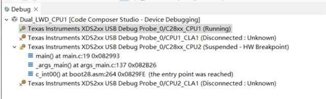
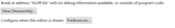

请问是哪里出问题了呢?

