

Part Number: LAUNCHXL-F28P55X
Other Parts Discussed in Thread: C2000WARE, UNIFLASH
软件环境:
CCS版本:Code Composer Studio 12.8.1;
C2000ware :C2000Ware_5_04_00_00;
UniFlash :UniFlash 9.1.0;
硬件环境:
开发套件;
C2000 实时 MCU F28P55X LaunchPad 开发套件;
工程背景:
自己的工程基于".\C2000Ware_5_04_00_00\driverlib\f28p55x\examples\sci\sci_ex1_loopback"导入,成功实现官方直接存储器存取 (DMA) 实验".\C2000Ware_5_04_00_00\training\device\f28p55x\advance_topics\lab_dma\lab_dma_launchpad",此时工程下载与调试均正常。
问题背景:
在将基于官方例程的RFFT功能迁移到自己的工程后,编译器没有报错,程序成功下载,但是下载之后开发板卡死。
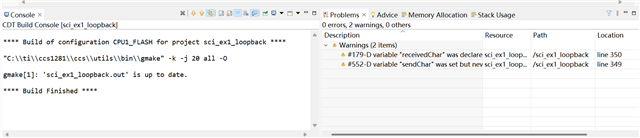
之后尝试再次进行程序下载与调试,工程编译均无报错,有警告(警告为有两个变量未使用),但是再也无法将该程序成功下载到开发板。
尝试更换为官方例程led_ex1_blinky,也无法下载到开发板,具有相同报错。
尝试使用UniFlash观察寄存器值,擦除FLASH等操作,均报错无法执行。
更换开发板,在烧录该问题工程之前,新开发板都可以正常使用(包括官方例程),烧录该工程之后出现与第一块开发板同样的问题。
具体报错:
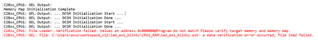
当使用RAM模式编译工程后,下载时报错如下:
C28xx_CPU1: GEL Output: Memory Map Initialization Complete C28xx_CPU1: GEL Output: ... DCSM Initialization Start ... C28xx_CPU1: GEL Output: ... DCSM Initialization Done ... C28xx_CPU1: GEL Output: ... DCSM Initialization Start ... C28xx_CPU1: GEL Output: ... DCSM Initialization Done ... C28xx_CPU1: File Loader: Verification failed: Values at address 0x000000@Program do not match Please verify target memory and memory map. C28xx_CPU1: GEL: File: C:\Users\asus\workspace_v12\led_ex1_blinky\CPU1_RAM\led_ex1_blinky.out: a data verification error occurred, file load failed.
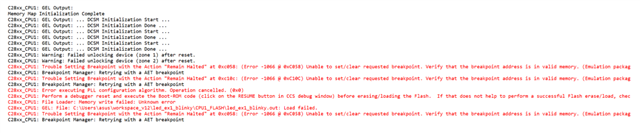
当使用FLASH模式编译工程后,下载时报错如下:
C28xx_CPU1: GEL Output: Memory Map Initialization Complete C28xx_CPU1: GEL Output: ... DCSM Initialization Start ... C28xx_CPU1: GEL Output: ... DCSM Initialization Done ... C28xx_CPU1: GEL Output: ... DCSM Initialization Start ... C28xx_CPU1: GEL Output: ... DCSM Initialization Done ... C28xx_CPU1: GEL Output: ... DCSM Initialization Start ... C28xx_CPU1: GEL Output: ... DCSM Initialization Done ... C28xx_CPU1: Warning: Failed unlocking device (zone 1) after reset. C28xx_CPU1: Warning: Failed unlocking device (zone 2) after reset. C28xx_CPU1: Trouble Setting Breakpoint with the Action "Remain Halted" at 0xc058: (Error -1066 @ 0xC058) Unable to set/clear requested breakpoint. Verify that the breakpoint address is in valid memory. (Emulation package 20.0.0.3178) C28xx_CPU1: Breakpoint Manager: Retrying with a AET breakpoint C28xx_CPU1: Trouble Setting Breakpoint with the Action "Remain Halted" at 0xc10c: (Error -1066 @ 0xC10C) Unable to set/clear requested breakpoint. Verify that the breakpoint address is in valid memory. (Emulation package 20.0.0.3178) C28xx_CPU1: Breakpoint Manager: Retrying with a AET breakpoint C28xx_CPU1: Error executing PLL configuration algorithm. Operation cancelled. (0x0) C28xx_CPU1: Perform a debugger reset and execute the Boot-ROM code (click on the RESUME button in CCS debug window) before erasing/loading the Flash. If that does not help to perform a successful Flash erase/load, check the Reset cause (RESC) register, NMI shadow flag (NMISHDFLG) register and the Boot-ROM status register for further debug. C28xx_CPU1: File Loader: Memory write failed: Unknown error C28xx_CPU1: GEL: File: C:\Users\asus\workspace_v12\led_ex1_blinky\CPU1_FLASH\led_ex1_blinky.out: Load failed. C28xx_CPU1: Trouble Setting Breakpoint with the Action "Remain Halted" at 0xc058: (Error -1066 @ 0xC058) Unable to set/clear requested breakpoint. Verify that the breakpoint address is in valid memory. (Emulation package 20.0.0.3178) C28xx_CPU1: Breakpoint Manager: Retrying with a AET breakpoint
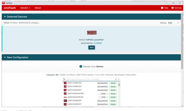
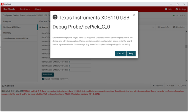
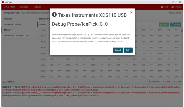
使用UniFlash,可以识别开发板但是无法连接,具体如下 :
[2025/5/8 下午10:36:38] [ERROR] IcePick_C_0: Error connecting to the target: (Error -2131 @ 0x0) Unable to access device register. Reset the device, and retry the operation. If error persists, confirm configuration, power-cycle the board, and/or try more reliable JTAG settings (e.g. lower TCLK). (Emulation package 20.1.0.3372)
可以识别到开发板
擦除FLASH时报错如下
读取寄存器时报错相同
问题工程主函数代码
//
// Included Files
//
#include "driverlib.h"
#include "device.h"
#include "board.h"

#include "c2000ware_libraries.h"

#include <stdio.h>
#include <string.h>
#include <stdarg.h>
#include <stddef.h>
#include <stdlib.h>
#include <math.h>

#include "tjc_usart_hmi.h"
//
// Globals
//
uint16_t loopCount;
uint16_t errorCount;

//
// Function Prototypes
//
void error();

//变量定义
#define FRAME_LENGTH 7
volatile uint32_t delay_times = 0;
volatile uint8_t uart_data = 0;
volatile uint32_t now_time = 0;

int a = 100;
char str[100]={0};
uint32_t last_time = 0;

//曲线测试变量
int add_i=0;
int addt_i=0;
//串口中断测试变量
int rx_interrupt_cnt=0;
//函数定义
// 搭配滴答定时器实现的精确ms延时
void delay_ms(uint32_t ms)
{
    while(ms--)
    {
        DEVICE_DELAY_US(1000);  // 每次延时 1000 微秒 = 1 毫秒
    }
}
//定时器变量
uint16_t timer_1s=0;
//
// ADC变量
//
uint16_t myADC0Result0;
uint16_t myADC0Result1;

volatile float myADC0Result0_double=0;
volatile float myADC0Result1_double=0;

////epwm中断测试变量
int dma_interrupt_cnt=0;
//DMA ADC配置
#define ADC_BUF_LEN 1024              // Buffer length.

#pragma DATA_SECTION(AdcBufRaw, "ramgs0");
#pragma DATA_SECTION(AdcBuf, "ramgs1");
uint16_t AdcBufRaw[2*ADC_BUF_LEN];  // The ping-pong buffer.
uint16_t AdcBuf[ADC_BUF_LEN];       // Buffer for CCS plotting.
uint16_t PingPongState = 0;         // ping-pong buffer state.
uint16_t LedCtr = 0;                // Counter to slow LED toggling.
uint16_t TaskDelayUs = 0;           // Delay to simulate data processing task.
uint16_t OverCnt = 0;               // Counter to store DMA overwrites.
uint32_t TimDiff;                   // To measure the DMA ISR time.

const void* AdcAddr = (void*)(ADCARESULT_BASE + ADC_O_RESULT0);
const void* AdcRawBufAddr = (void*)AdcBufRaw;

//FFT
//*****************************************************************************
// 宏定义
//*****************************************************************************
#define RFFT_STAGES     8
#define RFFT_SIZE       (1 << RFFT_STAGES)
#define EPSILON         0.01
//#define USE_TABLE   // 如果使用预定义的FFT旋转因子表,请在 sysconfig 中勾选 "Use Predefined Twiddle Factors"

//*****************************************************************************
// 全局变量
//*****************************************************************************
#ifdef __cplusplus
#pragma DATA_SECTION("RFFTdata1")
#pragma DATA_SECTION("RFFTdata2")
#pragma DATA_SECTION("RFFTdata3")
#else
#pragma DATA_SECTION(RFFTin1Buff,"RFFTdata1")
#pragma DATA_SECTION(RFFTmagBuff,"RFFTdata2")
#pragma DATA_SECTION(RFFTphBuff,"RFFTdata3")
#pragma DATA_SECTION(RFFToutBuff,"RFFTdata4")
#endif //__cplusplus

//! \brief FFT计算输入缓冲区
//! \note 输入缓冲区需按 2N 字对齐
//! \note 如果FFT级数为奇数,最终输出结果也会写回此缓冲区
float32_t RFFTin1Buff[RFFT_SIZE];
float32_t* inPtr = RFFTin1Buff;

//! \brief 幅值计算缓冲区
float32_t RFFTmagBuff[RFFT_SIZE/2+1];
float32_t* magPtr = RFFTmagBuff;

//! \brief 相位计算缓冲区
float32_t RFFTphBuff[RFFT_SIZE/2];
float32_t* phPtr = RFFTphBuff;

//! \brief FFT计算输出缓冲区
//! \note 如果FFT级数为偶数,结果将写入此缓冲区
float32_t RFFToutBuff[RFFT_SIZE];
float32_t* outPtr = RFFToutBuff;

// 包含参考输出数据
float32_t RFFTgoldenOut[RFFT_SIZE] = {
    #include "data_output_rfft1.h"
};

float32_t RFFTgoldenMagnitude[RFFT_SIZE/2+1] = {
    #include "data_output_rfft2.h"
};

float32_t RFFTgoldenPhase[RFFT_SIZE/2] = {
    #include "data_output_rfft3.h"
};

// FFT旋转因子表
float32_t RFFTTwiddleCoef[RFFT_SIZE];
float32_t* twiddlePtr = RFFTTwiddleCoef;

// 用于生成输入信号的步进参数
float32_t RadStep = 0.1963495408494f;
float32_t Rad = 0.0f;

// 测试统计
uint16_t pass = 0;
uint16_t fail = 0;

int rfft_fpu32_test(void)
{
    // 清除输入缓冲区
    memset(inPtr, 0, RFFT_SIZE*sizeof(float32_t));
    memset(magPtr, 0, (RFFT_SIZE/2+1)*sizeof(float32_t));
    memset(phPtr, 0, RFFT_SIZE/2*sizeof(float32_t));
    memset(outPtr, 0, RFFT_SIZE/2*sizeof(float32_t));

    // 生成输入波形
    int i;
    Rad = 0.0f;
    for(i = 0; i < RFFT_SIZE; i++)
    {
        RFFTin1Buff[i] = sinf(Rad) + cosf(Rad*2.3567); // 生成实数输入信号
        Rad = Rad + RadStep;
    }

    //
    // 离位计算算法(Off-Place)
    //
    // 注意:
    // 在此版本中,RFFTinBuff 和 RFFToutBuff 采用乒乓存取方式。
    // 初始数据存入 RFFTin1Buff,FFT及位反转排序初步完成。
    // 随着每一级FFT,CurrentInPtr和CurrentOutPtr指针交替切换。
    // 最终输出将根据FFT级数的奇偶性存储在RFFTin1Buff(奇数)或RFFToutBuff(偶数)。
    //
    // cfft对象的初始化由sysconfig完成。
    //
    // 注意:
    // RFFT_f32要求输入缓冲区地址对齐到2N字。
    // 如果无法对齐,可以使用性能较低的RFFT_f32u函数。

    RFFT_f32(myRFFT0_handle);  // 计算实数FFT

    // 检查FFT输出结果
    for(i = 0; i < RFFT_SIZE; i++){
        if(fabsf(RFFTgoldenOut[i] - myRFFT0_handle->OutBuf[i]) <= EPSILON){
            pass++;
        } else {
            fail++;
        }
    }

    // 输出缓冲区结构示例:
    // OutBuf[0] = 实部[0]
    // OutBuf[1] = 实部[1]
    // OutBuf[2] = 实部[2]
    // ...
    // OutBuf[N/2] = 实部[N/2]
    // OutBuf[N/2+1] = 虚部[N/2-1]
    // ...
    // OutBuf[N-3] = 虚部[3]
    // OutBuf[N-2] = 虚部[2]
    // OutBuf[N-1] = 虚部[1]

#ifdef __TMS320C28XX_TMU__
    RFFT_f32_mag_TMU0(myRFFT0_handle);  // 使用TMU0计算幅值
#else
    RFFT_f32_mag(myRFFT0_handle);       // 计算幅值
#endif

    // 检查幅值输出
    for(i = 0; i <= RFFT_SIZE/2; i++){
        if(fabsf(RFFTgoldenMagnitude[i] - myRFFT0_handle->MagBuf[i]) <= EPSILON){
            pass++;
        } else {
            fail++;
        }
    }

#ifdef __TMS320C28XX_TMU__
    RFFT_f32_phase_TMU0(myRFFT0_handle); // 使用TMU0计算相位
#else
    RFFT_f32_phase(myRFFT0_handle);      // 计算相位
#endif

    // 检查相位输出
    for(i = 0; i < RFFT_SIZE/2; i++){
        if(fabsf(RFFTgoldenPhase[i] - myRFFT0_handle->PhaseBuf[i]) <= EPSILON){
            pass++;
        } else {
            fail++;
        }
    }

    //printf("测试通过:%d 项,失败:%d 项\n", pass, fail);

    return 1;
}


//
// Main
//
void main(void)
{
    uint16_t sendChar;
    uint16_t receivedChar;

    //
    // Initialize device clock and peripherals
    //
    Device_init();

    //
    // Setup GPIO by disabling pin locks and enabling pullups
    //
    Device_initGPIO();

    //
    // Initialize PIE and clear PIE registers. Disables CPU interrupts.
    //
    Interrupt_initModule();

    // Initialize the PIE vector table with pointers to the shell Interrupt
    // Service Routines (ISR).
    //
    Interrupt_initVectorTable();

    //
    // Board Initialization
    //
    Board_init();

    //
    // Enables CPU interrupts
    //
    Interrupt_enableGlobal();

    //
    // Initialize counts
    //

    SysCtl_enablePeripheral(SYSCTL_PERIPH_CLK_TBCLKSYNC);

    loopCount = 0;
    errorCount = 0;

    //
    // Send a character starting with 0
    //
    sendChar = 0;

    //
    // Send Characters forever starting with 0x00 and going through 0xFF.
    // After sending each, check the receive buffer for the correct value.
    //
    //
    // Enable Global Interrupt (INTM) and real time interrupt (DBGM)
    //
    EINT;
    ERTM;
    initRingBuff();

    rfft_fpu32_test();

//    Interrupt_enable(INT_mySCI0_TX);
//    Interrupt_enable(INT_mySCI0_RX);
    for(;;)
    {
        if(timer_1s>=1000)
        {
            timer_1s=0;


            myADC0Result0 = ADC_readResult(ADCARESULT_BASE, ADC_SOC_NUMBER0);
//            myADC0Result1 = ADC_readResult(ADCARESULT_BASE, ADC_SOC_NUMBER1);
//
            myADC0Result0_double=(myADC0Result0*3.3/4096.0);
//            myADC0Result1_double=myADC0Result1*3.3/4096.0;


        //串口发送测试
        //数字
//        sprintf(str, "n0.val=1");
//        tjc_send_string(str);
        sprintf(str, "n0.val=%d",rx_interrupt_cnt);
        tjc_send_string(str);

        //文本


        //sprintf(str, "t1.txt=\"%.2f\"",myADC0Result0_double);
        //sprintf(str, "t1.txt=\"%d\"",(int)myADC0Result0_double);
        floatToString(str, "t1.txt=\"", myADC0Result0_double, "\"", 2);
        tjc_send_string(str);
        sprintf(str, "t2.txt=\"%d\"",dma_interrupt_cnt);
        tjc_send_string(str);
//        TJCPrintf("t1.txt=\"%d\"",(int)myADC0Result0_double);
//        sprintf(str, "t2.txt=\"%.2lf\"",myADC0Result1_double);
        tjc_send_string(str);

        //曲线 清空
        sprintf(str, "cle s0.id,0");
        tjc_send_string(str);
        //曲线 单点添加
        for(add_i =0;add_i<GRAPH_LENTH;add_i++)
        {
            //向曲线s0的通道0传输1个数据,add指令不支持跨页面
            sprintf(str,"add s0.id,0,%d",(int)(AdcBuf[GRAPH_LENTH-1-add_i]/16));
            tjc_send_string(str);
        }

        //曲线 清空
        sprintf(str, "cle s0.id,1");
        tjc_send_string(str);
        //曲线 单点添加
        for(add_i =0;add_i<GRAPH_LENTH;add_i++)
        {
            //向曲线s0的通道0传输1个数据,add指令不支持跨页面
            sprintf(str,"add s0.id,1,%d",(int)(RFFTgoldenMagnitude[GRAPH_LENTH-1-add_i]));
            tjc_send_string(str);
        }


        // 当串口缓冲区大于等于一帧的长度时
        while (usize >= FRAME_LENGTH)
        {
            // 校验帧头帧尾是否匹配
            if (usize >= FRAME_LENGTH && u(0) == 0x55 && u(4) == 0xff && u(5) == 0xff && u(6) == 0xff)
            {
                // 匹配,进行解析
                if (u(2) == 0x01)
                {
                    sprintf(str, "t0.txt=\"1\"");
                    tjc_send_string(str);

                }
                else if (u(2) == 0x02)
                {
                    // 下发的是h0进度条的信息

                    sprintf(str, "t0.txt=\"2\"");
                    tjc_send_string(str);
                }
                else if (u(2) == 0x03)
                {
                    // 下发的是h1进度条的信息
                    sprintf(str, "t0.txt=\"3\"");
                    tjc_send_string(str);
                }

                udelete(7); // 删除解析过的数据
            }
            else
            {

                // 不匹配删除1字节
                udelete(1);
                break;
            }
        }

        }
        //delay_ms(1000);

    }
}

//
// cpuTimer0ISR - Counter for CpuTimer0
//
__interrupt void INT_myCPUTIMER0_ISR(void)
{
    timer_1s++;

    //
    // Acknowledge this interrupt to receive more interrupts from group 1
    //
    Interrupt_clearACKGroup(INTERRUPT_ACK_GROUP1);
}


// 接收中断服务例程
__interrupt void INT_mySCI0_RX_ISR(void)
{
    rx_interrupt_cnt=(rx_interrupt_cnt+1)%256;

    if(SCI_getRxFIFOStatus(SCIA_BASE)!=SCI_FIFO_RX0)
    {
        // 中断处理代码(例如读取接收到的数据)

        // 接发送过来的数据保存在变量中
        uart_data = SCI_readCharNonBlocking(SCIA_BASE);
        // 将保存的数据再发送出去
        // uart0_send_char(uart_data);
        writeRingBuff(uart_data);


    }
    SCI_clearOverflowStatus(mySCI0_BASE);
    SCI_clearInterruptStatus(mySCI0_BASE, SCI_INT_RXFF);
    Interrupt_clearACKGroup(INTERRUPT_ACK_GROUP9);

}

// 发送中断服务例程
//__interrupt void INT_mySCI0_TX_ISR(void)
//{
//    // 中断处理代码(例如发送数据)
//    rx_interrupt_cnt=(rx_interrupt_cnt+1)%256;
//    SCI_clearInterruptStatus(SCIA_BASE, SCI_INT_TXFF);
//    //Interrupt_clearACKGroup(INTERRUPT_ACK_GROUP9);
//
//}


//__interrupt void INT_myEPWM0_ISR(void)
//{
//
//    Interrupt_clearACKGroup(INTERRUPT_ACK_GROUP2);
//}


interrupt void INT_myDMA0_ISR(void)
{
    dma_interrupt_cnt=(dma_interrupt_cnt+1)%256;

    // Clear the interrupt flags.
    Interrupt_clearACKGroup(INTERRUPT_ACK_GROUP7);

    // Start and reload the timer.
    //CPUTimer_startTimer(myCPUTIMER0_BASE);

    uint16_t *AdcBufPtr = AdcBuf;
    uint16_t *AdcBufRawPtr;
    uint16_t i;

    // Blink LED at about 1Hz. ISR is occurring every 1ms.
    if (LedCtr++ >= 50) {
        GPIO_togglePin(myBoardLED1_GPIO);
        LedCtr = 0;
    }

    if (PingPongState == 0) {
        // Set DMA address to start at ping buffer.
        DMA_configAddresses(DMA_CH1_BASE,
                            (const void *)AdcBufRaw,
                            (const void *)(ADCARESULT_BASE + ADC_O_RESULT0));

        // Fill AdcBuf with contents of the pong buffer.
        AdcBufRawPtr = AdcBufRaw + ADC_BUF_LEN;
        for (i = 0; i < ADC_BUF_LEN; i++) {
            *(AdcBufPtr++) = *(AdcBufRawPtr++);
        }
    } else {
        // Set DMA address to start at pong buffer.
        DMA_configAddresses(DMA_CH1_BASE,
                            (const void *)(AdcBufRaw + ADC_BUF_LEN),
                            (const void *)(ADCARESULT_BASE + ADC_O_RESULT0));

        // Fill AdcBuf with contents on the ping buffer.
        AdcBufRawPtr = AdcBufRaw;
        for (i = 0; i < ADC_BUF_LEN; i++) {
            *(AdcBufPtr++) = *(AdcBufRawPtr++);
        }
    }

    // Toggle PingPongState.
    PingPongState ^= 1;

    // Delay to simulate more data processing.
    for (i = 0; i < TaskDelayUs; i++) {
        DEVICE_DELAY_US(1);
    }

    // Get the time stamp and check to see if interrupt completed within the
    // required time frame of 1ms. Don't worry about overflows.
    //CPUTimer_stopTimer(myCPUTIMER0_BASE);
    TimDiff = 0xFFFFFFFF - CPUTimer_getTimerCount(myCPUTIMER0_BASE);
    if (TimDiff >= ((uint32_t)(0.001*DEVICE_SYSCLK_FREQ))) {
        OverCnt++;
    }
}

