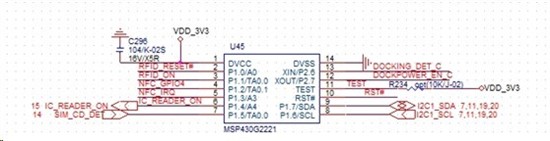
This thread has been locked.

If you have a related question, please click the "Ask a related question" button in the top right corner. The newly created question will be automatically linked to this question.

初学I2C通信问题(MSP430G2231)

Other Parts Discussed in Thread: MSP430G2231, MSP430G2221
我的MCUMSP430G2231,电路大概是这样的:
这里我想要实现的功能是:MCU通过I2CARM相连进行通信

(1)       ARM系统通知MCU上电或下电RFID/IC等,

(2)       MCU通知ARM系统SIM卡已上电。

这样双向通信的话,对于MSP430来说,
1)只用一根SDA线可以吗? 还是需要一根SDAIN,一根SDAOUT
2)没很搞明白Master/slave中的receive操作和Transmitter操作请问的两种操作这里只用Master中的receive操作和Transmitter操作就可以接收吗?还是属于Master中的receive操作和Slave中的Transmitter操作
3)看了很久Family User Guide中的I2C原理还是没搞明白其初始化以及传输流程,感觉晕晕的,里面的示例代码全是汇编的如果有C代码对照着看起来就好多了有哪位可以帮我讲讲吗
4)正常的程序流程是,先初始化I2C,然后程序进入while(1),然后根据USI中断进行数据的处理,这里我的问题是:a. 怎么去使I2C的状态在master/slave中的发送/接收状态变换?
5I2C上的数据通过什么去获取?一次可以传几位啊?
这里真的是刚接触,问题有点多,请多见谅或多或少的解答都很感谢您!
  •  

    Kyle wang 说:
    1)只用一根SDA线可以吗? 还是需要一根SDAIN,一根SDAOUT

    不行!数据线是一条SDA,双向的,还需要一条CLK。这个可以去查看I2C协议;

    Kyle wang 说:
    2)没很搞明白Master/slave中的receive操作和Transmitter操作请问的两种操作这里只用Master中的receive操作和Transmitter操作就可以接收吗?还是属于Master中的receive操作和Slave中的Transmitter操作

    在7位地址后面有一个bit用于标识读或者写。您就当成一个主人在向奴隶征收租子,主人负责发号施令,奴隶跟着执行就行了。

    因为MSP430可以作为master或者slave嘛,所以程序编写的时候肯定会不一样。所以如果您MSP430做主机,主要看Master 接收和发送部分就可以了。

    Kyle wang 说:
    3)看了很久Family User Guide中的I2C原理还是没搞明白其初始化以及传输流程,感觉晕晕的,里面的示例代码全是汇编的如果有C代码对照着看起来就好多了有哪位可以帮我讲讲吗

    您好!在做I2C之前,先去研究I2C的协议。有中文版的。看完协议以后,MSP430的初始化,以及状态机就很简单了。

    Kyle wang 说:
    4)正常的程序流程是,先初始化I2C,然后程序进入while(1),然后根据USI中断进行数据的处理,这里我的问题是:a. 怎么去使I2C的状态在master/slave中的发送/接收状态变换?

    查看第2条

    Kyle wang 说:
    5I2C上的数据通过什么去获取?一次可以传几位啊?

    一次8bit。建议您花时间看协议。


  • (1)我图中有I2C_SCL,应该就是您说所的CLK吧?
    (2)大概有点明白,对我来说,MSP430就是跑程序的地方,肯定只要作为Master用来做接收(指令)和发送(指令)即可,无需用到slave。
    (3)我百度了下I2C协议,状态机大概明白了,感谢您!就是对初始化以及众寄存器的使用上,还得总对照着头文件看,有时也会乱乱的...

    另外,有新的问题求教:
    (4)我如何知道slave在通过I2C传MSP430传数据呢?是不是一旦slave或master有给I2C发数据,就会有一个USI中断产生呢?
    (5)我的slave和写数据地址是多少?是连接I2C_SDA这个引脚的地址吗?
    (6)那怎么在一个状态机中同时控制Master的发送和传输啊?

  • 你如果要是问这些问题的话,说明协议没有好好看啊!

  • 建议楼主应该找个资料先好好搞清楚I2C的硬件结构,数据传输方式。这样对您的提问更有帮助。即使解答您上面所有问题,相信您还是得自己慢慢消化。

  • 您好!谢谢你们的建议!我也有在看,但是还是不知道slave address是多少...求教...

    另外,我想把各引脚的状态(用status记录)保存起来,以便下次开机的时候恢复,并且通知上层系统。是不是在status变化的时候,需要把status写入内存flash中才能固化保存呢?


  • 下面是一个C语音的例程,可供参考:

    //******************************************************************************

    //  MSP430G2x21/G2x31 Demo - I2C Master Receiver, single byte

    //

    //  Description: I2C Master communicates with I2C Slave using

    //  the USI. Slave data should increment from 0x00 with each transmitted byte

    //  which is verified by the Master.

    //  LED off for address or data Ack; LED on for address or data NAck.

    //  ACLK = n/a, MCLK = SMCLK = Calibrated 1MHz

    //

    //  ***THIS IS THE MASTER CODE***

    //

    //                  Slave                      Master

    //          (msp430g2x21_usi_09.c)

    //            MSP430G2x21/G2x31           MSP430G2x21/G2x31

    //             -----------------          -----------------

    //         /|\|              XIN|-    /|\|              XIN|-

    //          | |                 |      | |                 |

    //          --|RST          XOUT|-     --|RST          XOUT|-

    //            |                 |        |                 |

    //      LED <-|P1.0             |        |                 |

    //            |                 |        |             P1.0|-> LED

    //            |         SDA/P1.7|------->|P1.7/SDA         |

    //            |         SCL/P1.6|<-------|P1.6/SCL         |

    //

    //  Note: internal pull-ups are used in this example for SDA & SCL

    //

    //  D. Dang

    //  Texas Instruments Inc.

    //  October 2010

    //  Built with CCS Version 4.2.0 and IAR Embedded Workbench Version: 5.10

    //******************************************************************************

    #include <msp430g2221.h>

    char SLV_data = 0x00;                  // Variable for received data

    char SLV_Addr = 0x91;                  // Address is 0x48 << 1 bit + 1 for Read

    int I2C_State = 0;                     // State variable

    void main(void)

    {

     volatile unsigned int i;             // Use volatile to prevent removal

     WDTCTL = WDTPW + WDTHOLD;            // Stop watchdog

     if (CALBC1_1MHZ ==0xFF || CALDCO_1MHZ == 0xFF)                                    

     {  

       while(1);                          // If calibration constants are erased

                                          // do not load, trap CPU!!

     }

     BCSCTL1 = CALBC1_1MHZ;               // Set DCO

     DCOCTL = CALDCO_1MHZ;

     P1OUT = 0xC0;                        // P1.6 & P1.7 Pullups

     P1REN |= 0xC0;                       // P1.6 & P1.7 Pullups

     P1DIR = 0xFF;                        // Unused pins as outputs

     P2OUT = 0;

     P2DIR = 0xFF;

     USICTL0 = USIPE6+USIPE7+USIMST+USISWRST;// Port & USI mode setup

     USICTL1 = USII2C+USIIE;              // Enable I2C mode & USI interrupt

     USICKCTL = USIDIV_3+USISSEL_2+USICKPL;// Setup USI clocks: SCL = SMCLK/8 (~120kHz)

     USICNT |= USIIFGCC;                  // Disable automatic clear control

     USICTL0 &= ~USISWRST;                // Enable USI

     USICTL1 &= ~USIIFG;                  // Clear pending flag

     _EINT();

     while(1)

     {

       USICTL1 |= USIIFG;                 // Set flag and start communication

       LPM0;                              // CPU off, await USI interrupt

       _NOP();                            // Used for IAR

       for (i = 0; i < 5000; i++);        // Dummy delay between communication cycles

     }

    }

    /******************************************************

    // USI interrupt service routine

    ******************************************************/

    #pragma vector = USI_VECTOR

    __interrupt void USI_TXRX (void)

    {

     switch(I2C_State)

       {

         case 0: // Generate Start Condition & send address to slave

                 P1OUT |= 0x01;           // LED on: sequence start

                 USISRL = 0x00;           // Generate Start Condition...

                 USICTL0 |= USIGE+USIOE;

                 USICTL0 &= ~USIGE;

                 USISRL = SLV_Addr;       // ... and transmit address, R/W = 1

                 USICNT = (USICNT & 0xE0) + 0x08; // Bit counter = 8, TX Address

                 I2C_State = 2;           // Go to next state: receive address (N)Ack

                 break;

         case 2: // Receive Address Ack/Nack bit

                 USICTL0 &= ~USIOE;       // SDA = input

                 USICNT |= 0x01;          // Bit counter = 1, receive (N)Ack bit

                 I2C_State = 4;           // Go to next state: check (N)Ack

                 break;

         case 4: // Process Address Ack/Nack & handle data RX

                 if (USISRL & 0x01)       // If Nack received...

                 { // Prep Stop Condition

                   USICTL0 |= USIOE;

                   USISRL = 0x00;

                   USICNT |=  0x01;       // Bit counter = 1, SCL high, SDA low

                   I2C_State = 10;        // Go to next state: generate Stop

                   P1OUT |= 0x01;         // Turn on LED: error

                 }

                 else                     // Ack received

                 { // Receive Data from slave

                   USICNT |=  0x08;       // Bit counter = 8, RX data

                   I2C_State = 6;         // Go to next state: Test data and (N)Ack

                   P1OUT &= ~0x01;        // LED off

                 }

                 break;

         case 6: // Send Data Ack/Nack bit

                 USICTL0 |= USIOE;        // SDA = output

                 if (USISRL == SLV_data)  // If data valid...

                 {

                   USISRL = 0x00;         // Send Ack

                   SLV_data++;            // Increment Slave data

                   P1OUT &= ~0x01;        // LED off

                 }

                 else

                 {

                   USISRL = 0xFF;         // Send NAck

                   P1OUT |= 0x01;         // LED on: error

                 }

                 USICNT |= 0x01;          // Bit counter = 1, send (N)Ack bit

                 I2C_State = 8;           // Go to next state: prep stop

                 break;

         case 8: // Prep Stop Condition

                 USICTL0 |= USIOE;        // SDA = output

                 USISRL = 0x00;

                 USICNT |=  0x01;         // Bit counter = 1, SCL high, SDA low

                 I2C_State = 10;          // Go to next state: generate Stop

                 break;

         case 10: // Generate Stop Condition

                 USISRL = 0x0FF;          // USISRL = 1 to release SDA

                 USICTL0 |= USIGE;        // Transparent latch enabled

                 USICTL0 &= ~(USIGE+USIOE);// Latch/SDA output disabled

                 I2C_State = 0;           // Reset state machine for next transmission

                 LPM0_EXIT;               // Exit active for next transfer

                 break;

       }

     USICTL1 &= ~USIIFG;                  // Clear pending flag

    }

  • 1.根据你的原理图是接的MCU的USI的IIC功能,如果使用USI配置成IIC使用,则SDA是主机从机共用数据线,除非是将其用作IO口模拟SPI总线用或者UART用则是需要一去一来两根数据线,当然从你提供的原理图和说明看,应该是当IIC总线用;

    2.master transmitter -> slave receiver, master receiver <- slave transmitter, 就这两种模式

    3.TI官网上有USI实现IIC的例程,可以下下来看看。

    4.转换发送接收状态,设置USICTL0中USIOE置一则设置为输出-发送,置零则设置为输入-接收;

    5.在成功握手后,如果数据发送到接收到完成接收(移位寄存器完成),则会置USIIFG位,进入中断读取USISRL的值,IIC协议一次传输8个bit数据。

  • Leon Yan提供了一段Master receiver的代码,这里是一段slave transmitter的代码,分别烧进两个MCU,

    把两个MCU的IIC接口用线连起来就可以正常通讯了,用逻辑分析仪可以看到通讯时的波形

    //******************************************************************************

    //  MSP430G2x21/G2x31 Demo - I2C Slave Transmitter, single byte

    //

    //  Description: I2C Slave communicates with I2C Master using

    //  the USI. Slave data is sent and increments from 0x00 with each transmitted

    //  byte which is verified by the Master.

    //  LED off for address or data Ack; LED on for address or data NAck.

    //  ACLK = n/a, MCLK = SMCLK = Calibrated 1MHz

    //

    //  ***THIS IS THE SLAVE CODE***

    //

    //                  Slave                      Master

    //                                      (msp430g2x21_usi_06.c)

    //             MSP430G2x21/G2x31          MSP430G2x21/G2x31

    //             -----------------          -----------------

    //         /|\|              XIN|-    /|\|              XIN|-

    //          | |                 |      | |                 |

    //          --|RST          XOUT|-     --|RST          XOUT|-

    //            |                 |        |                 |

    //      LED <-|P1.0             |        |                 |

    //            |                 |        |             P1.0|-> LED

    //            |         SDA/P1.7|------->|P1.7/SDA         |

    //            |         SCL/P1.6|<-------|P1.6/SCL         |

    //

    //  Note: internal pull-ups are used in this example for SDA & SCL

    //

    //  D. Dang

    //  Texas Instruments Inc.

    //  October 2010

    //  Built with CCS Version 4.2.0 and IAR Embedded Workbench Version: 5.10

    //******************************************************************************

    #include <msp430g2221.h>

    char SLV_Data = 0;                     // Variable for transmitted data

    char SLV_Addr = 0x90;                  // Address is 0x48<<1 for R/W

    int I2C_State = 0;                     // State variable

    void main(void)

    {

     WDTCTL = WDTPW + WDTHOLD;            // Stop watchdog

     if (CALBC1_1MHZ ==0xFF || CALDCO_1MHZ == 0xFF)                                    

     {  

       while(1);                          // If calibration constants erased

                                          // do not load, trap CPU!!

     }  

     BCSCTL1 = CALBC1_1MHZ;               // Set DCO

     DCOCTL = CALDCO_1MHZ;

     P1OUT = 0xC0;                        // P1.6 & P1.7 Pullups

     P1REN |= 0xC0;                       // P1.6 & P1.7 Pullups

     P1DIR = 0xFF;                        // Unused pins as outputs

     P2OUT = 0;

     P2DIR = 0xFF;

     USICTL0 = USIPE6+USIPE7+USISWRST;    // Port & USI mode setup

     USICTL1 = USII2C+USIIE+USISTTIE;     // Enable I2C mode & USI interrupts

     USICKCTL = USICKPL;                  // Setup clock polarity

     USICNT |= USIIFGCC;                  // Disable automatic clear control

     USICTL0 &= ~USISWRST;                // Enable USI

     USICTL1 &= ~USIIFG;                  // Clear pending flag

     _EINT();

     while(1)

     {

       LPM0;                              // CPU off, await USI interrupt

       _NOP();                            // Used for IAR

     }

    }

    //******************************************************

    // USI interrupt service routine

    //******************************************************

    #pragma vector = USI_VECTOR

    __interrupt void USI_TXRX (void)

    {

     if (USICTL1 & USISTTIFG)             // Start entry?

     {

       P1OUT |= 0x01;                     // LED on: Sequence start

       I2C_State = 2;                     // Enter 1st state on start

     }

     switch(I2C_State)

       {

         case 0: //Idle, should not get here

                 break;

         case 2: //RX Address

                 USICNT = (USICNT & 0xE0) + 0x08; // Bit counter = 8, RX Address

                 USICTL1 &= ~USISTTIFG;   // Clear start flag

                 I2C_State = 4;           // Go to next state: check address

                 break;

         case 4: // Process Address and send (N)Ack

                 if (USISRL & 0x01)       // If read...

                   SLV_Addr++;            // Save R/W bit

                 USICTL0 |= USIOE;        // SDA = output

                 if (USISRL == SLV_Addr)  // Address match?

                 {

                   USISRL = 0x00;         // Send Ack

                   P1OUT &= ~0x01;        // LED off

                   I2C_State = 8;         // Go to next state: TX data

                 }

                 else

                 {

                   USISRL = 0xFF;         // Send NAck

                   P1OUT |= 0x01;         // LED on: error

                   I2C_State = 6;         // Go to next state: prep for next Start

                 }

                 USICNT |= 0x01;          // Bit counter = 1, send (N)Ack bit

                 break;

         case 6: // Prep for Start condition

                 USICTL0 &= ~USIOE;       // SDA = input

                 SLV_Addr = 0x90;         // Reset slave address

                 I2C_State = 0;           // Reset state machine

                 break;

         case 8: // Send Data byte

                 USICTL0 |= USIOE;        // SDA = output

                 USISRL = SLV_Data;       // Send data byte

                 USICNT |=  0x08;         // Bit counter = 8, TX data

                 I2C_State = 10;          // Go to next state: receive (N)Ack

                 break;

         case 10:// Receive Data (N)Ack

                 USICTL0 &= ~USIOE;       // SDA = input

                 USICNT |= 0x01;          // Bit counter = 1, receive (N)Ack

                 I2C_State = 12;          // Go to next state: check (N)Ack

                 break;

         case 12:// Process Data Ack/NAck

                 if (USISRL & 0x01)       // If Nack received...

                 {

                   P1OUT |= 0x01;         // LED on: error

                 }

                 else                     // Ack received

                 {

                   P1OUT &= ~0x01;        // LED off

                   SLV_Data++;            // Increment Slave data

                 }

                 // Prep for Start condition

                 USICTL0 &= ~USIOE;       // SDA = input

                 SLV_Addr = 0x90;         // Reset slave address

                 I2C_State = 0;           // Reset state machine

                 break;

       }

     USICTL1 &= ~USIIFG;                  // Clear pending flags

    }

  • 4.是否在传数据可以通过检测是否哟USI中断发生和buffer是否有数据进行;

    5.slave地址是自己规定的,需要在通讯的第一个字节进行配对,主机一定要知道从机的地址;

    6.一个状态机中实现发送和接受,那就要合理设计这个状态机,USI是一个建议的是实现IIC和SPI的模块,要自己加很多标志位和控制状态机的流程,比较复杂,特别要注意状态的转换流程。

  • 非常地感谢大家的热心解答!我已经大概明白其原理和流程了,再问一个问题:
    我想实现:按键1.5按下时通过I2C发送Data给slave。并随时接收来自slave的I2C数据。数据都是1个byte的
    那我如下程序是否可以用来实现上述功能。有哪里错误需要修改吗?

      while(1)
      {
    // receive I2C Data
      DataDirection = Receive;
      USICTL1 |= USIIFG;                      // Set flag and start communication
      LPM0;                                   // CPU off, await USI interrupt
      __no_operation();
      for (i = 0; i < 5000; i++);        // Dummy delay between communication cycles
      }

    #pragma vector=PORT1_VECTOR
    __interrupt void PORT1_ISR(void)
    {
      P1IE &= ~BIT5;  //disable 1.5 interrupt
      if((P1IFG & BIT5) == BIT5)
      {//send I2C Data
      DataDirection = Transmit;
      USICTL1 |= USIIFG;                      // Set flag and start communication
      LPM0;                                   // CPU off, await USI interrupt 
      __no_operation();
      }
      P1IE |= BIT5; //enable 1.5 interrupt
    }

    //下面是个I2C中断状态机控制,太长先不贴出来

  • 先用自己搭的系统调试一下嘛,你看哪个地方不对时再问,回答时会有有针对性一些

  • 请问,MSP430的code examples 也就是代码库在哪里?一直没找到,求地址,谢谢~

  • 如果你用的ccs,默认安装时就有mspware的。

    如果不是用的ccs,可以看在线版的mspware

    http://dev.ti.com/tirex/#/Package/MSPWare?link=MSPWare