Other Parts Discussed in Thread: BQ40Z50, MSP430G2755, BQSTUDIO
HI,TI
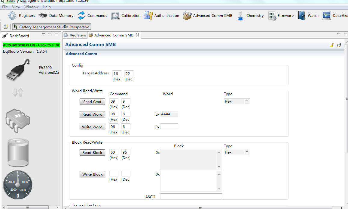
MSP430G2755做主机模拟I2C读取BQ40Z50已通讯成功。现需要实现430 USCI硬件I2C做从机,地址为0X16,用EV2300去读,430程序总是跑飞,一直执行RX中断。下面是通讯测试code,请TI大神帮忙看看,困了一周了。
TI有没有EV2300做主机,430做从机的USCI I2C例程。
#include "io430.h"
unsigned char *PRxData; // Pointer to RX data
unsigned char RXByteCtr;
volatile unsigned char RxBuffer[128]; // Allocate 128 byte of RAM
#define CPU_F ((double)1000000)//1MHZ
//#define CPU_F ((double)8000000)//8MHZ
#define delay_us(x) __delay_cycles((long)(CPU_F*(double)x/1000000.0))
#define delay_ms(x) __delay_cycles((long)(CPU_F*(double)x/1000.0))
int main( void )
{
// Stop watchdog timer to prevent time out reset
WDTCTL = WDTPW + WDTHOLD;
BCSCTL1 = CALBC1_1MHZ; // Set DCO to 1MHz 频率校准
DCOCTL = CALDCO_1MHZ;
BCSCTL1 &=~XTS; //XT1低频模式
BCSCTL1 |= DIVA_0 + XT2OFF; //关闭XT2,XT1不分频
BCSCTL2 |= SELM_0 + DIVM_0 + DIVS_0;//+ SELS //MCLK选择DCO时钟,不分频,SMCLK选择DCO,不分频
BCSCTL3 |= XT2S_2 + LFXT1S_2; //XT2频率范围为3MHz到16MHz,ACLK为VLO=12KHz
P3SEL |= 0x06; // Assign I2C pins to USCI_B0
UCB0CTL1 |= UCSWRST; // Enable SW reset
UCB0CTL0 |= UCMODE_3 + UCSYNC; // I2C Slave, synchronous mode
UCB0CTL1 |= UCSSEL_2 + UCSWRST; // Use SMCLK, keep SW reset
UCB0BR0 = 10; // Set prescaler 1M/10~100KHZ
UCB0BR1 = 0;
UCB0I2COA = 0x0B; // Own Address 0x16>>1
UCB0CTL1 &= ~UCSWRST; // Clear SW reset, resume operation
UCB0I2CIE |=UCSTPIE + UCSTTIE; // Enable STT, STP interrupt
IE2 |= UCB0RXIE; // Enable RX TX interrupt
P2DIR|=BIT3;//P2.3设置为输出
P2OUT|=BIT3;
P3DIR|=BIT5;//P3.5设置为输出
P3OUT|=BIT5;
__enable_interrupt(); // Enable GIE bit
while(1)
{
P3OUT^=BIT5;
delay_ms(100);
}
}
#pragma vector = USCIAB0RX_VECTOR
__interrupt void USCIAB0RX_ISR(void)
{
RxBuffer[RXByteCtr]= UCB0RXBUF; // Get RX'd byte into buffer
RXByteCtr++;
}