

使用的是msp430fr5969,程序为TI官方的例程,定义一个uint8_t类型的来存放获取的数据,uint8_t ReceiveBuffer[MAX_BUFFER_SIZE] = {0}; 初始化为0,未进行任何赋值情况下,输出值却是:1af8 。
进入中断函数时:接收中断:将UCB0RXBUF赋给ReceiveBuffer,直接printf(); 输出的是 0 (未调用UCB0RXBUF时,直接打印UCB0RXBUF,也是0),回到主函数输出ReceiveBuffer又是1af8,
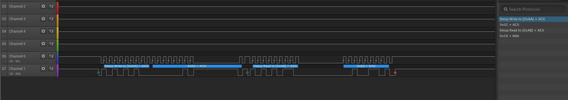
波形图和c文件附上,请问哪里出错了吗?
//******************************************************************************
// MSP430FR59xx Demo - eUSCI_B0, I2C Master multiple byte TX/RX
//
// Description: I2C master communicates to I2C slave sending and receiving
// 3 different messages of different length. I2C master will enter LPM0 mode
// while waiting for the messages to be sent/receiving using I2C interrupt.
// ACLK = NA, MCLK = SMCLK = DCO 16MHz.
//
// /|\ /|\
// MSP430FR5969 4.7k |
// ----------------- | 4.7k
// /|\ | P1.7|---+---|-- I2C Clock (UCB0SCL)
// | | | |
// ---|RST P1.6|-------+-- I2C Data (UCB0SDA)
// | |
// | |
// | |
// | |
// | |
// | |
//
// Nima Eskandari
// Texas Instruments Inc.
// April 2017
// Built with CCS V7.0
//******************************************************************************
//
//
// ������Ϊ��ȡSlaveAddress��ַ��0xaa
// reg addr��0x02 һ���ֽڵ�ֵ
// Ȼ��ͨ��Terminal I/O�����ֵ
//
//
#include <msp430.h>
#include <stdint.h>
#include <stdbool.h>
//******************************************************************************
// Example Commands ************************************************************
//******************************************************************************
#define SLAVE_ADDR 0x55 //7λ��ַ SlaveAddress + R/W == 8 bits(ϵͳ���Զ�����1λ���ٲ�R/W)
/* CMD_TYPE_X_SLAVE are example commands the master sends to the slave.
* The slave will send example SlaveTypeX buffers in response.
*
* CMD_TYPE_X_MASTER are example commands the master sends to the slave.
* The slave will initialize itself to receive MasterTypeX example buffers.
* */
#define SOC 0x02
#define VOL 0X08
#define CMD_TYPE_0_SLAVE 0
#define CMD_TYPE_1_SLAVE 1
#define CMD_TYPE_2_SLAVE 2
#define CMD_TYPE_0_MASTER 3
#define CMD_TYPE_1_MASTER 4
#define CMD_TYPE_2_MASTER 5
#define TYPE_0_LENGTH 1
#define TYPE_1_LENGTH 2
#define TYPE_2_LENGTH 6
#define MAX_BUFFER_SIZE 20
/* MasterTypeX are example buffers initialized in the master, they will be
* sent by the master to the slave.
* SlaveTypeX are example buffers initialized in the slave, they will be
* sent by the slave to the master.
* */
uint8_t MasterType2 [TYPE_2_LENGTH] = {'F', '4', '1', '9', '2', 'B'};
uint8_t MasterType1 [TYPE_1_LENGTH] = { 8, 9};
uint8_t MasterType0 [TYPE_0_LENGTH] = { 11};
uint8_t SlaveType2 [TYPE_2_LENGTH] = {0};
uint8_t SlaveType1 [TYPE_1_LENGTH] = {0};
uint8_t SlaveType0 [TYPE_0_LENGTH] = {0};
//******************************************************************************
// General I2C State Machine ***************************************************
//******************************************************************************
typedef enum I2C_ModeEnum{
IDLE_MODE,
NACK_MODE,
TX_REG_ADDRESS_MODE,
RX_REG_ADDRESS_MODE,
TX_DATA_MODE,
RX_DATA_MODE,
SWITCH_TO_RX_MODE,
SWITHC_TO_TX_MODE,
TIMEOUT_MODE
} I2C_Mode;
/* Used to track the state of the software state machine*/
I2C_Mode MasterMode = IDLE_MODE;
/* The Register Address/Command to use*/
uint8_t TransmitRegAddr = 0;
/* ReceiveBuffer: Buffer used to receive data in the ISR
* RXByteCtr: Number of bytes left to receive
* ReceiveIndex: The index of the next byte to be received in ReceiveBuffer
* TransmitBuffer: Buffer used to transmit data in the ISR
* TXByteCtr: Number of bytes left to transfer
* TransmitIndex: The index of the next byte to be transmitted in TransmitBuffer
* */
/** ReceiveBuffer��������ISR�н������ݵĻ�����
* RXByteCtr��ʣ����ֽ���
* ReceiveIndex����ReceiveBuffer��Ҫ���յ���һ���ֽڵ�����
* TransmitBuffer��������ISR�д������ݵĻ�����
* TXByteCtr��ʣ���ֽ�������
* TransmitIndex����TransmitBuffer��Ҫ���͵���һ���ֽڵ�����
* */
uint8_t ReceiveBuffer[MAX_BUFFER_SIZE] = {0};
uint8_t RXByteCtr = 0;
uint8_t ReceiveIndex = 0;
uint8_t TransmitBuffer[MAX_BUFFER_SIZE] = {0};
uint8_t TXByteCtr = 0;
uint8_t TransmitIndex = 0;
/* I2C Write and Read Functions */
/* For slave device with dev_addr, writes the data specified in *reg_data
*
* dev_addr: The slave device address.
* Example: SLAVE_ADDR
* reg_addr: The register or command to send to the slave.
* Example: CMD_TYPE_0_MASTER
* *reg_data: The buffer to write
* Example: MasterType0
* count: The length of *reg_data
* Example: TYPE_0_LENGTH
* */
I2C_Mode I2C_Master_WriteReg(uint8_t dev_addr, uint8_t reg_addr, uint8_t *reg_data, uint8_t count);
/* For slave device with dev_addr, read the data specified in slaves reg_addr.
* The received data is available in ReceiveBuffer
*
* dev_addr: The slave device address.
* Example: SLAVE_ADDR
* reg_addr: The register or command to send to the slave.
* Example: CMD_TYPE_0_SLAVE
* count: The length of data to read
* Example: TYPE_0_LENGTH
* */
I2C_Mode I2C_Master_ReadReg(uint8_t dev_addr, uint8_t reg_addr, uint8_t count);
void CopyArray(uint8_t *source, uint8_t *dest, uint8_t count);
I2C_Mode I2C_Master_ReadReg(uint8_t dev_addr, uint8_t reg_addr, uint8_t count)
{
/* Initialize state machine */ //��ʼ��״̬��
MasterMode = TX_REG_ADDRESS_MODE;
TransmitRegAddr = reg_addr;
RXByteCtr = count;
TXByteCtr = 0;
ReceiveIndex = 0;
TransmitIndex = 0;
/* Initialize slave address and interrupts */ //��ʼ���ӻ���ַ���ж�
// After initialization, master transmitter mode
// is initiated by writing the desired slave address to the UCBxI2CSA register
// ��ʼ����ͨ��������Ĵӵ�ַд��UCBxI2CSA�Ĵ����������������ģʽ
UCB0I2CSA = dev_addr;
UCB0IFG &= ~(UCTXIFG + UCRXIFG); // Clear any pending interrupts ����κι�����ж� / USCI B0�ж������Ĵ���
UCB0IE &= ~UCRXIE; // Disable RX interrupt
UCB0IE |= UCTXIE; // Enable TX interrupt
UCB0CTLW0 |= UCTR + UCTXSTT; // I2C TX, start condition
__bis_SR_register(LPM0_bits + GIE); // Enter LPM0 w/ interrupts
return MasterMode;
}
I2C_Mode I2C_Master_WriteReg(uint8_t dev_addr, uint8_t reg_addr, uint8_t *reg_data, uint8_t count)
{
/* Initialize state machine */
MasterMode = TX_REG_ADDRESS_MODE;
TransmitRegAddr = reg_addr;
//Copy register data to TransmitBuffer
CopyArray(reg_data, TransmitBuffer, count);
TXByteCtr = count;
RXByteCtr = 0;
ReceiveIndex = 0;
TransmitIndex = 0;
/* Initialize slave address and interrupts */
UCB0I2CSA = dev_addr;
UCB0IFG &= ~(UCTXIFG + UCRXIFG); // Clear any pending interrupts
UCB0IE &= ~UCRXIE; // Disable RX interrupt
UCB0IE |= UCTXIE; // Enable TX interrupt
UCB0CTLW0 |= UCTR + UCTXSTT; // I2C TX, start condition
__bis_SR_register(LPM0_bits + GIE); // Enter LPM0 w/ interrupts
return MasterMode;
}
void CopyArray(uint8_t *source, uint8_t *dest, uint8_t count)
{
uint8_t copyIndex = 0;
for (copyIndex = 0; copyIndex < count; copyIndex++)
{
dest[copyIndex] = source[copyIndex];
}
}
//******************************************************************************
// Device Initialization *******************************************************
//******************************************************************************
void initGPIO()
{
// Configure GPIO
P1OUT &= ~BIT0; // Clear P1.0 output latch
P1DIR |= BIT0; // For LED
P1SEL1 |= BIT6 | BIT7; // I2C pins
// Disable the GPIO power-on default high-impedance mode to activate
// previously configured port settings
PM5CTL0 &= ~LOCKLPM5;
}
void initClockTo16MHz()
{
// Configure one FRAM waitstate as required by the device datasheet for MCLK
// operation beyond 8MHz _before_ configuring the clock system.
FRCTL0 = FRCTLPW | NWAITS_1;
// Clock System Setup
CSCTL0_H = CSKEY >> 8; // Unlock CS registers
CSCTL1 = DCORSEL | DCOFSEL_4; // Set DCO to 16MHz
CSCTL2 = SELA__VLOCLK | SELS__DCOCLK | SELM__DCOCLK;
CSCTL3 = DIVA__1 | DIVS__1 | DIVM__1; // Set all dividers
CSCTL0_H = 0; // Lock CS registerss TI���̽�CS�ر�
}
void initI2C()
{
UCB0CTLW0 = UCSWRST; // Enable SW reset
// I2C MASTER SMCLK ͬ��
UCB0CTLW0 |= UCMODE_3 | UCMST | UCSSEL__SMCLK | UCSYNC; // I2C master mode, SMCLK
UCB0BRW = 160; // fSCL = SMCLK/160 = ~100kHz
UCB0I2CSA = SLAVE_ADDR; // Slave Address
UCB0CTLW0 &= ~UCSWRST; // Clear SW reset, resume operation
UCB0IE |= UCNACKIE;
}
//******************************************************************************
// Main ************************************************************************
// Send and receive three messages containing the example commands *************
//******************************************************************************
int main(void) {
WDTCTL = WDTPW | WDTHOLD; // Stop watchdog timer
initClockTo16MHz();
initGPIO();
initI2C();
printf("before:%x\r\n",ReceiveBuffer[0]);//��ʼ��Ϊ0�������������uint8_t���������ֵΪ 1af8
I2C_Master_ReadReg(SLAVE_ADDR, SOC, TYPE_0_LENGTH);
printf("after:%x\r\n",ReceiveBuffer[0]); //��ֵ�������Ϊ 1af8 ,�������ж������ֵΪ 0
//CopyArray(ReceiveBuffer, SlaveType0, TYPE_0_LENGTH);
//printf("SOC:%x\r\n",SlaveType0);
__bis_SR_register(LPM0_bits + GIE);
return 0;
}
//******************************************************************************
// I2C Interrupt ***************************************************************
//******************************************************************************
#if defined(__TI_COMPILER_VERSION__) || defined(__IAR_SYSTEMS_ICC__)
#pragma vector = USCI_B0_VECTOR
__interrupt void USCI_B0_ISR(void)
#elif defined(__GNUC__)
void __attribute__ ((interrupt(USCI_B0_VECTOR))) USCI_B0_ISR (void)
#else
#error Compiler not supported!
#endif
{
//Must read from UCB0RXBUF
uint8_t rx_val = 0;
switch(__even_in_range(UCB0IV, USCI_I2C_UCBIT9IFG))
{
case USCI_NONE: break; // Vector 0: No interrupts
case USCI_I2C_UCALIFG: break; // Vector 2: ALIFG
case USCI_I2C_UCNACKIFG: // Vector 4: NACKIFG
break;
case USCI_I2C_UCSTTIFG: break; // Vector 6: STTIFG
case USCI_I2C_UCSTPIFG: break; // Vector 8: STPIFG
case USCI_I2C_UCRXIFG3: break; // Vector 10: RXIFG3
case USCI_I2C_UCTXIFG3: break; // Vector 12: TXIFG3
case USCI_I2C_UCRXIFG2: break; // Vector 14: RXIFG2
case USCI_I2C_UCTXIFG2: break; // Vector 16: TXIFG2
case USCI_I2C_UCRXIFG1: break; // Vector 18: RXIFG1
case USCI_I2C_UCTXIFG1: break; // Vector 20: TXIFG1
case USCI_I2C_UCRXIFG0: // Vector 22: RXIFG0
rx_val = UCB0RXBUF;
//printf("VAL:%x\r\n",rx_val);
if (RXByteCtr)
{
ReceiveBuffer[ReceiveIndex++] = rx_val;
//printf("in:%x\r\n",ReceiveBuffer[0]);
RXByteCtr--;
}
if (RXByteCtr == 1)
{
UCB0CTLW0 |= UCTXSTP; //Transmit STOP
}
else if (RXByteCtr == 0)
{
UCB0IE &= ~UCRXIE; // : UART Receive Interrupt Enable
MasterMode = IDLE_MODE;
__bic_SR_register_on_exit(CPUOFF); // Exit LPM0
}
break;
case USCI_I2C_UCTXIFG0: // Vector 24: TXIFG0
switch (MasterMode)
{
case TX_REG_ADDRESS_MODE:
UCB0TXBUF = TransmitRegAddr;
if (RXByteCtr)
MasterMode = SWITCH_TO_RX_MODE; // Need to start receiving now ���������ݣ�UCTXIFG ϵͳ����1��
else
MasterMode = TX_DATA_MODE; // Continue to transmision with the data in Transmit Buffer
break;
case SWITCH_TO_RX_MODE:
UCB0IE |= UCRXIE; // Enable RX interrupt
UCB0IE &= ~UCTXIE; // Disable TX interrupt
UCB0CTLW0 &= ~UCTR; // Switch to receiver
MasterMode = RX_DATA_MODE; // State state is to receive data
UCB0CTLW0 |= UCTXSTT; // Send repeated start
if (RXByteCtr == 1)
{
//Must send stop since this is the N-1 byte
while((UCB0CTLW0 & UCTXSTT));
UCB0CTLW0 |= UCTXSTP; // Send stop condition
}
break;
case TX_DATA_MODE:
if (TXByteCtr)
{
UCB0TXBUF = TransmitBuffer[TransmitIndex++];
TXByteCtr--;
}
else
{
//Done with transmission
UCB0CTLW0 |= UCTXSTP; // Send stop condition
MasterMode = IDLE_MODE;
UCB0IE &= ~UCTXIE; // disable TX interrupt
__bic_SR_register_on_exit(CPUOFF); // Exit LPM0
}
break;
default:
__no_operation();
break;
}
break;
default: break;
}
}

