This thread has been locked.
If you have a related question, please click the "Ask a related question" button in the top right corner. The newly created question will be automatically linked to this question.
各位大神好,我想用MSP430F149控制一个8位的DAC,DAC每隔12或13来控制一个升压模块,430和DAC采用SPI串口通信,请问有关于SPI的例程吗,谢谢。
我基于MSP430控制TLV5616 DAC这个程序进行更改,想把控制16位的改成控制8位的,以下为程序。
// //* SWRST** please see MSP430x1xx Users Guide for description *//
//
// MSP430F149
// -----------------
// /|\| XIN|-
// | | | TLV5616
// --|RST XOUT|- -------------
// | P3.0|------>|FS OUT|--> ~ 390Hz
// | SIMO0/P3.1|------>|DIN |
// | UCLK0/P3.3|------>|SCLK CS|-|
// | | | | v
// M. Buccini
// Texas Instruments Inc.
// Feb 2005
// Built with CCE Version: 3.2.0 and IAR Embedded Workbench Version: 3.21A
//******************************************************************************
#include <msp430.h>
unsigned int pointer; // 16-bit value to write
//------------------------------------------------------------------------------
// 12-bit Sine Lookup table with 32 steps
static unsigned int Sin_tab[32] = {
0,
10,
16,
20,
25,
30,
35,
40,
45,
50,
60,
70,
75,
80,
85,
90,
100,
110,
120,
130,
140,
150,
160,
170,
180,
190,
200,
210,
220,
230,
240,
250
};
int main(void)
{
WDTCTL = WDTPW + WDTHOLD; // Stop WDT
P3SEL |= 0xA; // P3.1,3 SPI option select
P3DIR |= 0xB; // P3.0,1,3 output direction
P3OUT &= ~0x1; // FS reset
ME1 |= USPIE0; // Enable USART0 SPI
UCTL0 |= CHAR + SYNC + MM; // 8-bit SPI Master **SWRST**
UTCTL0 = CKPH + CKPL + SSEL1 + STC; // Inv. delayed, SMCLK, 3-pin
UBR00 = 0x2; // ACLK/2 for baud rate
UBR10 = 0x0; // ACLK/2 for baud rate
UMCTL0 = 0x0; // Clear modulation
UCTL0 &= ~SWRST; // Initialize USART state machine
pointer = 0; // Clear pointer
CCTL0 = CCIE; // CCR0 interrupt enabled
CCR0 = 64-1; // ~ 390Hz Clock period
TACTL = TASSEL_2 + MC_1; // SMCLK, Up-mode
__bis_SR_register(LPM0_bits + GIE); // Enter LPM0 w/ interrupt
}
// Timer A0 interrupt service routine
#if defined(__TI_COMPILER_VERSION__) || defined(__IAR_SYSTEMS_ICC__)
#pragma vector=TIMERA0_VECTOR
__interrupt void Timer_A(void)
#elif defined(__GNUC__)
void __attribute__ ((interrupt(TIMERA0_VECTOR))) Timer_A (void)
#else
#error Compiler not supported!
#endif
P3OUT |= 0x1; // FS set
TXBUF0 = Sin_tab[pointer];
pointer++;
pointer &= 0x1F;}
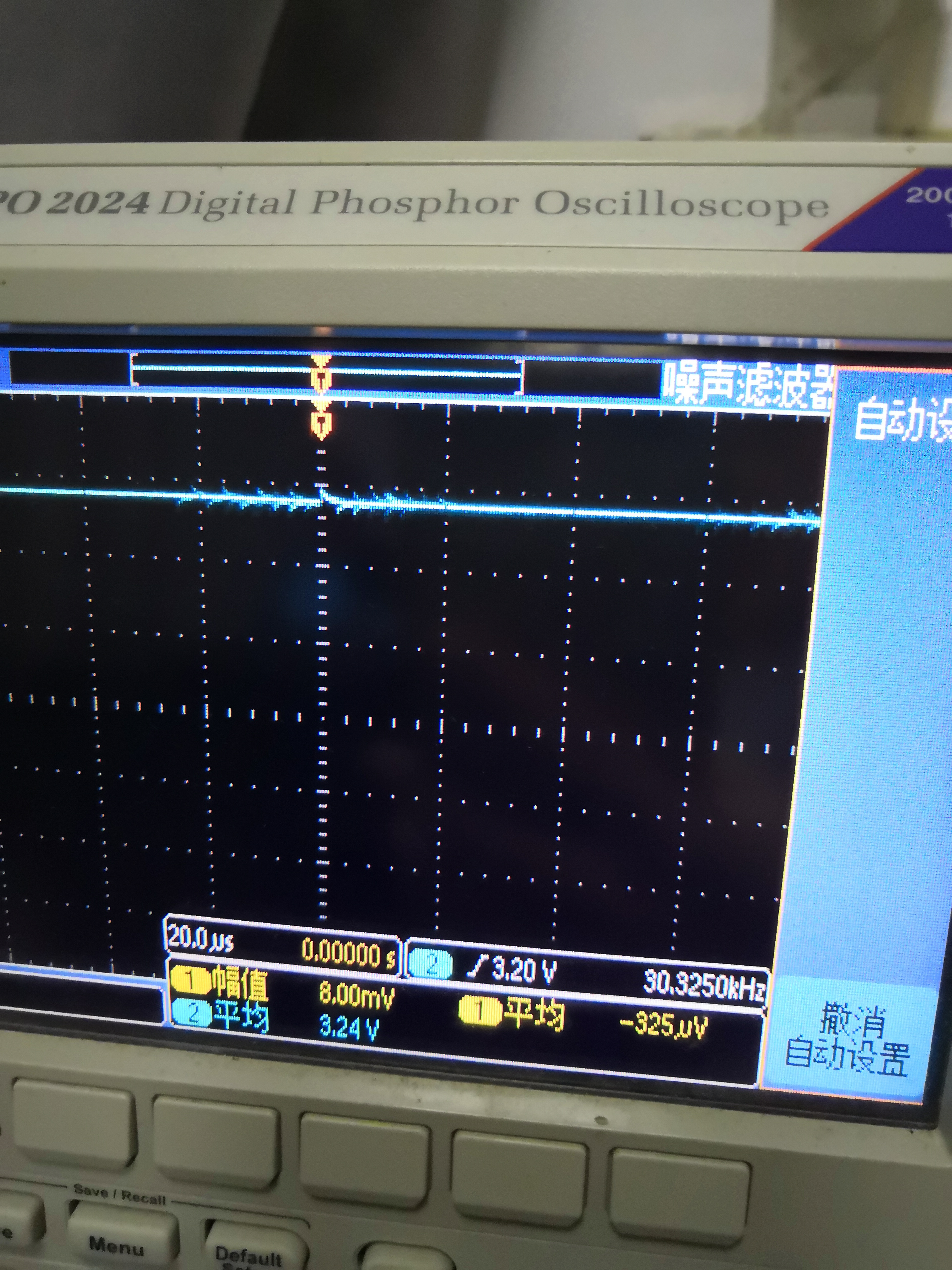
CS端口如图所示,片选并没有一个从高到低的过程
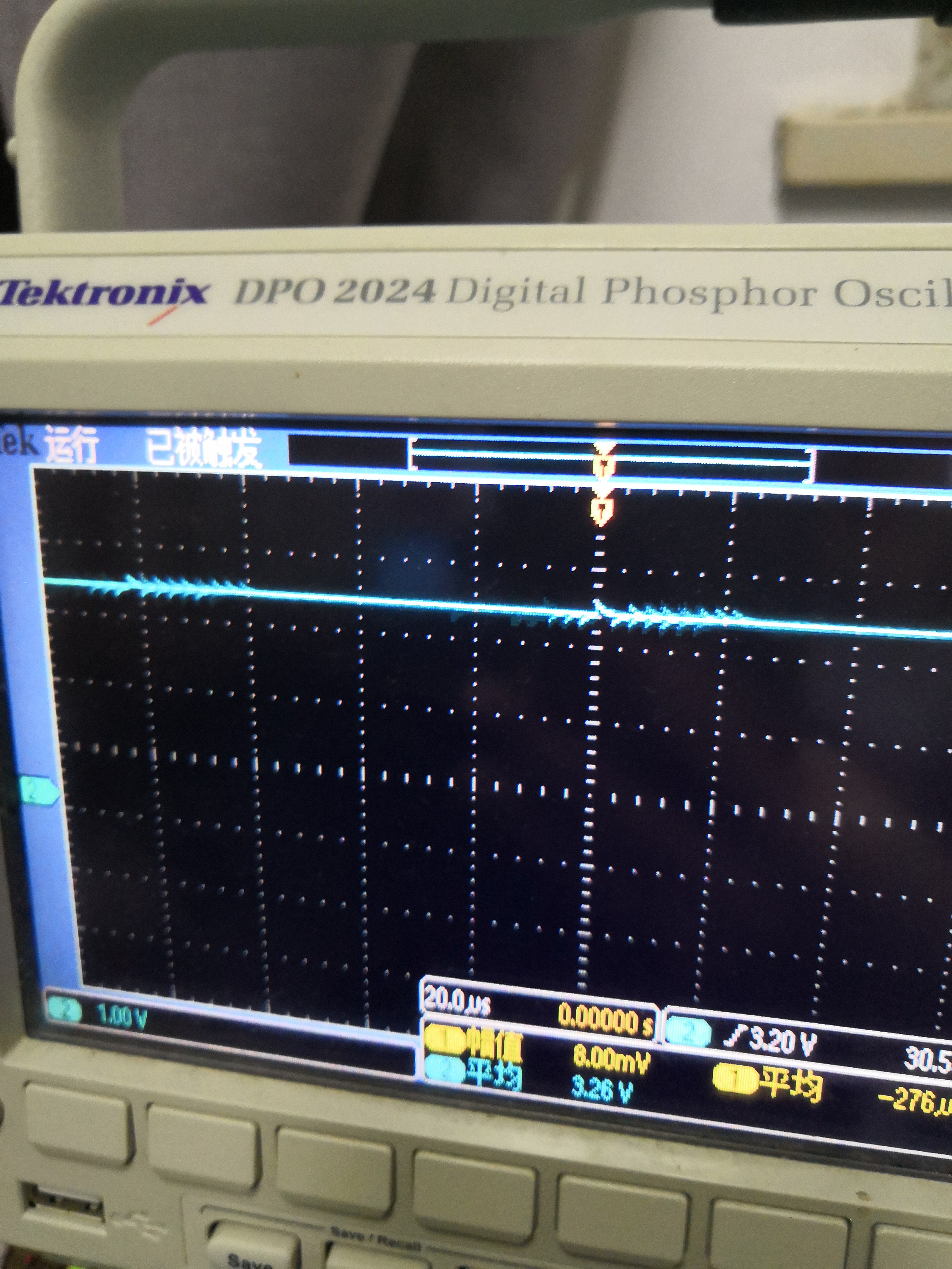
控制DIN的端口用示波器检测如图所示,
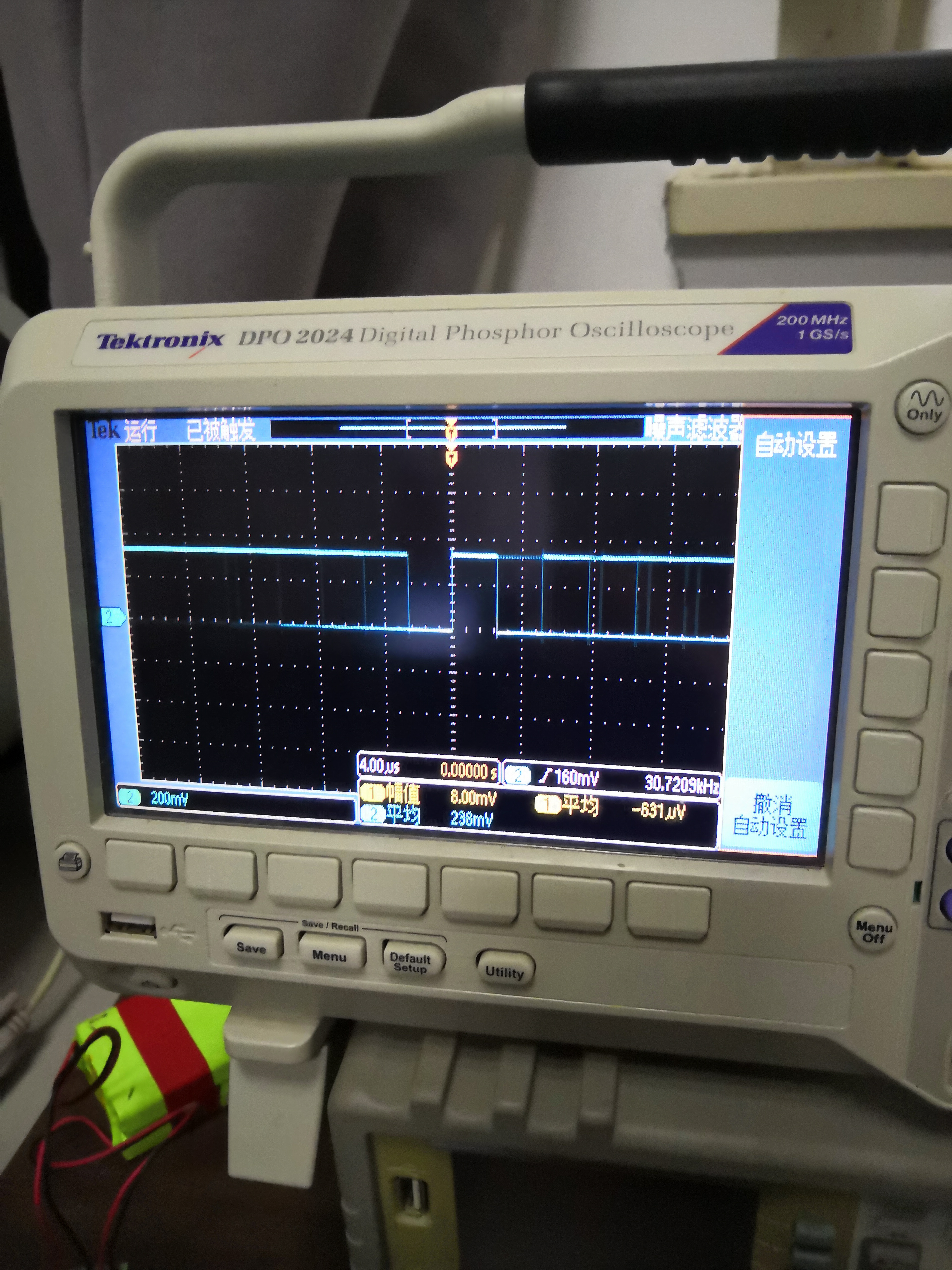
控制SCLK的端口如下图所示,也没有什么反应
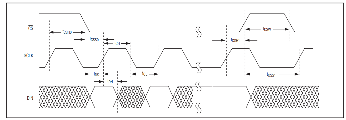
请问我是哪方面处理问题,下图是我要控制的8位DAC的时序图
谢谢