
This thread has been locked.

If you have a related question, please click the "Ask a related question" button in the top right corner. The newly created question will be automatically linked to this question.

MSP430G2553的硬件I2C没有发送起始条件

Other Parts Discussed in Thread: MSP430G2553

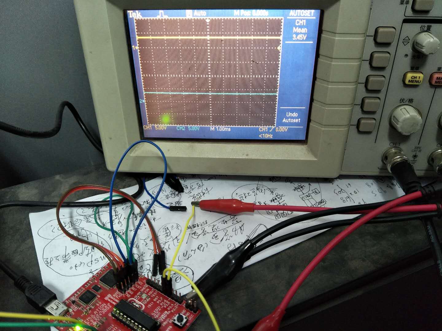
利用的是I2C例程:msp430g2xx3_uscib0_i2c_03,编译环境是IAR,P1.6为SCL,P1.7为SDA,利用示波器检测两引脚,执行 UCB0CTL1 |= UCTR + UCTXSTT;语句后  ,还一直是高电平。求各位大佬帮忙看一下,蟹蟹!~

程序如下:

#include <msp430.h>

const unsigned char Sine_Tab[] =

{
0xE5
};


int main(void)

{
WDTCTL = WDTPW + WDTHOLD;
P1DIR |=BIT0;
UCB0CTL1 |= UCSWRST;
UCB0CTL0 = UCMST + UCMODE_3 + UCSYNC;
P1SEL |= BIT6 + BIT7;
P1SEL2|= BIT6 + BIT7;
P1REN |= BIT6 + BIT7;


UCB0CTL1 = UCSSEL_2 + UCSWRST;
UCB0BR0 = 12;
UCB0BR1 = 0;
UCB0I2CSA = 0x40;
UCB0CTL1 &= ~UCSWRST;
IE2 |= UCB0TXIE;
UCB0CTL1 |= UCTR + UCTXSTT;
P1OUT ^=0x01;//p1.0
UCB0TXBUF = 0x010;
__bis_SR_register(CPUOFF + GIE);

}

#if defined(__TI_COMPILER_VERSION__) || defined(__IAR_SYSTEMS_ICC__)

#pragma vector = USCIAB0TX_VECTOR

__interrupt void USCIAB0TX_ISR(void)

#elif defined(__GNUC__)

void __attribute__ ((interrupt(USCIAB0TX_VECTOR))) USCIAB0TX_ISR (void)

#else

#error Compiler not supported!

#endif

{
static unsigned char ByteCtr;

UCB0TXBUF = Sine_Tab[ByteCtr++]; // Transmit data byte

ByteCtr &= 0x1f; // Do not exceed table
}
  • //******************************************************************************
    //   MSP430G2xx3 Demo - USCI_B0, I2C Master multiple byte TX/RX
    //
    //   Description: I2C master communicates to I2C slave sending and receiving
    //   3 different messages of different length. I2C master will enter LPM0 mode
    //   while waiting for the messages to be sent/receiving using I2C interrupt.
    //   ACLK = NA, MCLK = SMCLK = DCO 16MHz.
    //
    //
    //                   MSP430G2553         3.3V
    //                 -----------------   /|\ /|\
    //            /|\ |                 |   |  4.7k
    //             |  |                 |  4.7k |
    //             ---|RST              |   |   |
    //                |                 |   |   |
    //                |             P1.6|---|---+- I2C Clock (UCB0SCL)
    //                |                 |   |
    //                |             P1.7|---+----- I2C Data (UCB0SDA)
    //                |                 |
    //                |                 |
    //
    //   Nima Eskandari
    //   Texas Instruments Inc.
    //   April 2017
    //   Built with CCS V7.0
    //******************************************************************************
    
    #include <msp430.h>
    #include <stdint.h>
    #include <stdbool.h>
    
    //******************************************************************************
    // Example Commands ************************************************************
    //******************************************************************************
    
    #define SLAVE_ADDR  0x48
    
    /* CMD_TYPE_X_SLAVE are example commands the master sends to the slave.
     * The slave will send example SlaveTypeX buffers in response.
     *
     * CMD_TYPE_X_MASTER are example commands the master sends to the slave.
     * The slave will initialize itself to receive MasterTypeX example buffers.
     * */
    
    #define CMD_TYPE_0_SLAVE      0
    #define CMD_TYPE_1_SLAVE      1
    #define CMD_TYPE_2_SLAVE      2
    
    #define CMD_TYPE_0_MASTER      3
    #define CMD_TYPE_1_MASTER      4
    #define CMD_TYPE_2_MASTER      5
    
    #define TYPE_0_LENGTH   1
    #define TYPE_1_LENGTH   2
    #define TYPE_2_LENGTH   6
    
    #define MAX_BUFFER_SIZE     20
    
    /* MasterTypeX are example buffers initialized in the master, they will be
     * sent by the master to the slave.
     * SlaveTypeX are example buffers initialized in the slave, they will be
     * sent by the slave to the master.
     * */
    
    uint8_t MasterType2 [TYPE_2_LENGTH] = {'F', '4', '1', '9', '2', 'B'};
    uint8_t MasterType1 [TYPE_1_LENGTH] = { 8, 9};
    uint8_t MasterType0 [TYPE_0_LENGTH] = { 11};
    
    
    uint8_t SlaveType2 [TYPE_2_LENGTH] = {0};
    uint8_t SlaveType1 [TYPE_1_LENGTH] = {0};
    uint8_t SlaveType0 [TYPE_0_LENGTH] = {0};
    
    //******************************************************************************
    // General I2C State Machine ***************************************************
    //******************************************************************************
    
    
    typedef enum I2C_ModeEnum{
        IDLE_MODE,
        NACK_MODE,
        TX_REG_ADDRESS_MODE,
        RX_REG_ADDRESS_MODE,
        TX_DATA_MODE,
        RX_DATA_MODE,
        SWITCH_TO_RX_MODE,
        SWITHC_TO_TX_MODE,
        TIMEOUT_MODE
    } I2C_Mode;
    
    
    /* Used to track the state of the software state machine*/
    I2C_Mode MasterMode = IDLE_MODE;
    
    /* The Register Address/Command to use*/
    uint8_t TransmitRegAddr = 0;
    
    /* ReceiveBuffer: Buffer used to receive data in the ISR
     * RXByteCtr: Number of bytes left to receive
     * ReceiveIndex: The index of the next byte to be received in ReceiveBuffer
     * TransmitBuffer: Buffer used to transmit data in the ISR
     * TXByteCtr: Number of bytes left to transfer
     * TransmitIndex: The index of the next byte to be transmitted in TransmitBuffer
     * */
    uint8_t ReceiveBuffer[MAX_BUFFER_SIZE] = {0};
    uint8_t RXByteCtr = 0;
    uint8_t ReceiveIndex = 0;
    uint8_t TransmitBuffer[MAX_BUFFER_SIZE] = {0};
    uint8_t TXByteCtr = 0;
    uint8_t TransmitIndex = 0;


    /* I2C Write and Read Functions */
    
    /* For slave device with dev_addr, writes the data specified in *reg_data
     *
     * dev_addr: The slave device address.
     *           Example: SLAVE_ADDR
     * reg_addr: The register or command to send to the slave.
     *           Example: CMD_TYPE_0_MASTER
     * *reg_data: The buffer to write
     *           Example: MasterType0
     * count: The length of *reg_data
     *           Example: TYPE_0_LENGTH
     *  */
    I2C_Mode I2C_Master_WriteReg(uint8_t dev_addr, uint8_t reg_addr, uint8_t *reg_data, uint8_t count);
    
    /* For slave device with dev_addr, read the data specified in slaves reg_addr.
     * The received data is available in ReceiveBuffer
     *
     * dev_addr: The slave device address.
     *           Example: SLAVE_ADDR
     * reg_addr: The register or command to send to the slave.
     *           Example: CMD_TYPE_0_SLAVE
     * count: The length of data to read
     *           Example: TYPE_0_LENGTH
     *  */
    I2C_Mode I2C_Master_ReadReg(uint8_t dev_addr, uint8_t reg_addr, uint8_t count);
    void CopyArray(uint8_t *source, uint8_t *dest, uint8_t count);
    
    
    I2C_Mode I2C_Master_ReadReg(uint8_t dev_addr, uint8_t reg_addr, uint8_t count)
    {
        /* Initialize state machine */
        MasterMode = TX_REG_ADDRESS_MODE;
        TransmitRegAddr = reg_addr;
        RXByteCtr = count;
        TXByteCtr = 0;
        ReceiveIndex = 0;
        TransmitIndex = 0;
    
        /* Initialize slave address and interrupts */
        UCB0I2CSA = dev_addr;
        IFG2 &= ~(UCB0TXIFG + UCB0RXIFG);       // Clear any pending interrupts
        IE2 &= ~UCB0RXIE;                       // Disable RX interrupt
        IE2 |= UCB0TXIE;                        // Enable TX interrupt
    
        UCB0CTL1 |= UCTR + UCTXSTT;             // I2C TX, start condition
        __bis_SR_register(CPUOFF + GIE);              // Enter LPM0 w/ interrupts
    
        return MasterMode;
    
    }
    
    
    I2C_Mode I2C_Master_WriteReg(uint8_t dev_addr, uint8_t reg_addr, uint8_t *reg_data, uint8_t count)
    {
        /* Initialize state machine */
        MasterMode = TX_REG_ADDRESS_MODE;
        TransmitRegAddr = reg_addr;
    
        //Copy register data to TransmitBuffer
        CopyArray(reg_data, TransmitBuffer, count);
    
        TXByteCtr = count;
        RXByteCtr = 0;
        ReceiveIndex = 0;
        TransmitIndex = 0;
    
        /* Initialize slave address and interrupts */
        UCB0I2CSA = dev_addr;
        IFG2 &= ~(UCB0TXIFG + UCB0RXIFG);       // Clear any pending interrupts
        IE2 &= ~UCB0RXIE;                       // Disable RX interrupt
        IE2 |= UCB0TXIE;                        // Enable TX interrupt
    
        UCB0CTL1 |= UCTR + UCTXSTT;             // I2C TX, start condition
        __bis_SR_register(CPUOFF + GIE);              // Enter LPM0 w/ interrupts
    
        return MasterMode;
    }
    
    
    void CopyArray(uint8_t *source, uint8_t *dest, uint8_t count)
    {
        uint8_t copyIndex = 0;
        for (copyIndex = 0; copyIndex < count; copyIndex++)
        {
            dest[copyIndex] = source[copyIndex];
        }
    }


    //******************************************************************************
    // Device Initialization *******************************************************
    //******************************************************************************
    
    
    void initClockTo16MHz()
    {
        if (CALBC1_16MHZ==0xFF)                  // If calibration constant erased
        {
            while(1);                               // do not load, trap CPU!!
        }
        DCOCTL = 0;                               // Select lowest DCOx and MODx settings
        BCSCTL1 = CALBC1_16MHZ;                    // Set DCO
        DCOCTL = CALDCO_16MHZ;
    }
    
    void initGPIO()
    {
        P1DIR |= BIT0 + BIT1 + BIT2 + BIT3 + BIT4;
        P1OUT &= ~(BIT0 + BIT1 + BIT2 + BIT3 + BIT4);
    
        P1SEL |= BIT6 + BIT7;                     // Assign I2C pins to USCI_B0
        P1SEL2|= BIT6 + BIT7;                     // Assign I2C pins to USCI_B0
    }
    
    void initI2C()
    {
        UCB0CTL1 |= UCSWRST;                      // Enable SW reset
        UCB0CTL0 = UCMST + UCMODE_3 + UCSYNC;     // I2C Master, synchronous mode
        UCB0CTL1 = UCSSEL_2 + UCSWRST;            // Use SMCLK, keep SW reset
        UCB0BR0 = 160;                            // fSCL = SMCLK/160 = ~100kHz
        UCB0BR1 = 0;
        UCB0I2CSA = SLAVE_ADDR;                   // Slave Address
        UCB0CTL1 &= ~UCSWRST;                     // Clear SW reset, resume operation
        UCB0I2CIE |= UCNACKIE;
    }
    
    
    //******************************************************************************
    // Main ************************************************************************
    // Send and receive three messages containing the example commands *************
    //******************************************************************************
    
    int main(void) {
    
        WDTCTL = WDTPW | WDTHOLD;	              // Stop watchdog timer
    
        initClockTo16MHz();
        initGPIO();
        initI2C();
    
    
        I2C_Master_WriteReg(SLAVE_ADDR, CMD_TYPE_0_MASTER, MasterType0, TYPE_0_LENGTH);
        I2C_Master_WriteReg(SLAVE_ADDR, CMD_TYPE_1_MASTER, MasterType1, TYPE_1_LENGTH);
        I2C_Master_WriteReg(SLAVE_ADDR, CMD_TYPE_2_MASTER, MasterType2, TYPE_2_LENGTH);
    
        I2C_Master_ReadReg(SLAVE_ADDR, CMD_TYPE_0_SLAVE, TYPE_0_LENGTH);
        CopyArray(ReceiveBuffer, SlaveType0, TYPE_0_LENGTH);
    
        I2C_Master_ReadReg(SLAVE_ADDR, CMD_TYPE_1_SLAVE, TYPE_1_LENGTH);
        CopyArray(ReceiveBuffer, SlaveType1, TYPE_1_LENGTH);
    
        I2C_Master_ReadReg(SLAVE_ADDR, CMD_TYPE_2_SLAVE, TYPE_2_LENGTH);
        CopyArray(ReceiveBuffer, SlaveType2, TYPE_2_LENGTH);
    
        __bis_SR_register(LPM0_bits + GIE);
    	return 0;
    }
    
    
    //******************************************************************************
    // I2C Interrupt For Received and Transmitted Data******************************
    //******************************************************************************
    
    #if defined(__TI_COMPILER_VERSION__) || defined(__IAR_SYSTEMS_ICC__)
    #pragma vector = USCIAB0TX_VECTOR
    __interrupt void USCIAB0TX_ISR(void)
    #elif defined(__GNUC__)
    void __attribute__ ((interrupt(USCIAB0TX_VECTOR))) USCIAB0TX_ISR (void)
    #else
    #error Compiler not supported!
    #endif
    {
      if (IFG2 & UCB0RXIFG)                 // Receive Data Interrupt
      {
          //Must read from UCB0RXBUF
          uint8_t rx_val = UCB0RXBUF;
    
          if (RXByteCtr)
          {
              ReceiveBuffer[ReceiveIndex++] = rx_val;
              RXByteCtr--;
          }
    
          if (RXByteCtr == 1)
          {
              UCB0CTL1 |= UCTXSTP;
          }
          else if (RXByteCtr == 0)
          {
              IE2 &= ~UCB0RXIE;
              MasterMode = IDLE_MODE;
              __bic_SR_register_on_exit(CPUOFF);      // Exit LPM0
          }
      }
      else if (IFG2 & UCB0TXIFG)            // Transmit Data Interrupt
      {
          switch (MasterMode)
          {
              case TX_REG_ADDRESS_MODE:
                  UCB0TXBUF = TransmitRegAddr;
                  if (RXByteCtr)
                      MasterMode = SWITCH_TO_RX_MODE;   // Need to start receiving now
                  else
                      MasterMode = TX_DATA_MODE;        // Continue to transmision with the data in Transmit Buffer
                  break;
    
              case SWITCH_TO_RX_MODE:
                  IE2 |= UCB0RXIE;              // Enable RX interrupt
                  IE2 &= ~UCB0TXIE;             // Disable TX interrupt
                  UCB0CTL1 &= ~UCTR;            // Switch to receiver
                  MasterMode = RX_DATA_MODE;    // State state is to receive data
                  UCB0CTL1 |= UCTXSTT;          // Send repeated start
                  if (RXByteCtr == 1)
                  {
                      //Must send stop since this is the N-1 byte
                      while((UCB0CTL1 & UCTXSTT));
                      UCB0CTL1 |= UCTXSTP;      // Send stop condition
                  }
                  break;
    
              case TX_DATA_MODE:
                  if (TXByteCtr)
                  {
                      UCB0TXBUF = TransmitBuffer[TransmitIndex++];
                      TXByteCtr--;
                  }
                  else
                  {
                      //Done with transmission
                      UCB0CTL1 |= UCTXSTP;     // Send stop condition
                      MasterMode = IDLE_MODE;
                      IE2 &= ~UCB0TXIE;                       // disable TX interrupt
                      __bic_SR_register_on_exit(CPUOFF);      // Exit LPM0
                  }
                  break;
    
              default:
                  __no_operation();
                  break;
          }
      }
    }
    
    
    //******************************************************************************
    // I2C Interrupt For Start, Restart, Nack, Stop ********************************
    //******************************************************************************
    
    #if defined(__TI_COMPILER_VERSION__) || defined(__IAR_SYSTEMS_ICC__)
    #pragma vector = USCIAB0RX_VECTOR
    __interrupt void USCIAB0RX_ISR(void)
    #elif defined(__GNUC__)
    void __attribute__ ((interrupt(USCIAB0RX_VECTOR))) USCIAB0RX_ISR (void)
    #else
    #error Compiler not supported!
    #endif
    {
        if (UCB0STAT & UCNACKIFG)
        {
            UCB0STAT &= ~UCNACKIFG;             // Clear NACK Flags
        }
        if (UCB0STAT & UCSTPIFG)                        //Stop or NACK Interrupt
        {
            UCB0STAT &=
                ~(UCSTTIFG + UCSTPIFG + UCNACKIFG);     //Clear START/STOP/NACK Flags
        }
        if (UCB0STAT & UCSTTIFG)
        {
            UCB0STAT &= ~(UCSTTIFG);                    //Clear START Flags
        }
    }
    

  • //******************************************************************************
    //   MSP430G2xx3 Demo - USCI_B0, I2C Slave multiple byte TX/RX
    //
    //   Description: I2C master communicates to I2C slave sending and receiving
    //   3 different messages of different length. (This is the slave code). The
    //   slave will be in LPM0 mode, waiting for the master to initiate the
    //   communication. The slave will send/receive bytes based on the master's
    //   request. The slave will handle I2C bytes sent/received using the
    //   I2C interrupt.
    //   ACLK = NA, MCLK = SMCLK = DCO 16MHz.
    //
    //
    //                   MSP430G2553         3.3V
    //                 -----------------   /|\ /|\
    //            /|\ |                 |   |  4.7k
    //             |  |                 |  4.7k |
    //             ---|RST              |   |   |
    //                |                 |   |   |
    //                |             P1.6|---|---+- I2C Clock (UCB0SCL)
    //                |                 |   |
    //                |             P1.7|---+----- I2C Data (UCB0SDA)
    //                |                 |
    //                |                 |
    //
    //   Nima Eskandari
    //   Texas Instruments Inc.
    //   April 2017
    //   Built with CCS V7.0
    //******************************************************************************
    
    #include <msp430.h> 
    #include <stdint.h>
    
    
    //******************************************************************************
    // Example Commands ************************************************************
    //******************************************************************************
    
    #define SLAVE_ADDR  0x48
    
    /* CMD_TYPE_X_SLAVE are example commands the master sends to the slave.
     * The slave will send example SlaveTypeX buffers in response.
     *
     * CMD_TYPE_X_MASTER are example commands the master sends to the slave.
     * The slave will initialize itself to receive MasterTypeX example buffers.
     * */
    
    #define CMD_TYPE_0_SLAVE      0
    #define CMD_TYPE_1_SLAVE      1
    #define CMD_TYPE_2_SLAVE      2
    
    #define CMD_TYPE_0_MASTER      3
    #define CMD_TYPE_1_MASTER      4
    #define CMD_TYPE_2_MASTER      5
    
    #define TYPE_0_LENGTH   1
    #define TYPE_1_LENGTH   2
    #define TYPE_2_LENGTH   6
    
    #define MAX_BUFFER_SIZE     20
    
    /* MasterTypeX are example buffers initialized in the master, they will be
     * sent by the master to the slave.
     * SlaveTypeX are example buffers initialized in the slave, they will be
     * sent by the slave to the master.
     * */
    
    uint8_t MasterType2 [TYPE_2_LENGTH] = {0};
    uint8_t MasterType1 [TYPE_1_LENGTH] = { 0, 0};
    uint8_t MasterType0 [TYPE_0_LENGTH] = { 0};
    
    uint8_t SlaveType2 [TYPE_2_LENGTH] = {'A', 'B', 'C', 'D', '1', '2'};
    uint8_t SlaveType1 [TYPE_1_LENGTH] = {15, 16};
    uint8_t SlaveType0 [TYPE_0_LENGTH] = {12};
    
    
    //******************************************************************************
    // General I2C State Machine ***************************************************
    //******************************************************************************
    
    typedef enum I2C_ModeEnum{
        IDLE_MODE,
        NACK_MODE,
        TX_REG_ADDRESS_MODE,
        RX_REG_ADDRESS_MODE,
        TX_DATA_MODE,
        RX_DATA_MODE,
        SWITCH_TO_RX_MODE,
        SWITHC_TO_TX_MODE,
        TIMEOUT_MODE
    } I2C_Mode;
    
    /* Used to track the state of the software state machine*/
    I2C_Mode SlaveMode = RX_REG_ADDRESS_MODE;
    
    /* The Register Address/Command to use*/
    uint8_t ReceiveRegAddr = 0;
    
    /* ReceiveBuffer: Buffer used to receive data in the ISR
     * RXByteCtr: Number of bytes left to receive
     * ReceiveIndex: The index of the next byte to be received in ReceiveBuffer
     * TransmitBuffer: Buffer used to transmit data in the ISR
     * TXByteCtr: Number of bytes left to transfer
     * TransmitIndex: The index of the next byte to be transmitted in TransmitBuffer
     * */
    uint8_t ReceiveBuffer[MAX_BUFFER_SIZE] = {0};
    uint8_t RXByteCtr = 0;
    uint8_t ReceiveIndex = 0;
    uint8_t TransmitBuffer[MAX_BUFFER_SIZE] = {0};
    uint8_t TXByteCtr = 0;
    uint8_t TransmitIndex = 0;
    
    
    /* Initialized the software state machine according to the received cmd
     *
     * cmd: The command/register address received
     * */
    void I2C_Slave_ProcessCMD(uint8_t cmd);
    
    /* The transaction between the slave and master is completed. Uses cmd
     * to do post transaction operations. (Place data from ReceiveBuffer
     * to the corresponding buffer based in the last received cmd)
     *
     * cmd: The command/register address corresponding to the completed
     * transaction
     */
    void I2C_Slave_TransactionDone(uint8_t cmd);
    void CopyArray(uint8_t *source, uint8_t *dest, uint8_t count);
    
    
    void I2C_Slave_ProcessCMD(uint8_t cmd)
    {
        ReceiveIndex = 0;
        TransmitIndex = 0;
        RXByteCtr = 0;
        TXByteCtr = 0;
    
        switch (cmd)
        {
            case (CMD_TYPE_0_SLAVE):                        //Send slave device id (This device's id)
                SlaveMode = TX_DATA_MODE;
                TXByteCtr = TYPE_0_LENGTH;
                //Fill out the TransmitBuffer
                CopyArray(SlaveType0, TransmitBuffer, TYPE_0_LENGTH);
                IE2 &= ~UCB0RXIE;                       // Disable RX interrupt
                IE2 |= UCB0TXIE;                        // Enable TX interrupt
                break;
            case (CMD_TYPE_1_SLAVE):                      //Send slave device time (This device's time)
                SlaveMode = TX_DATA_MODE;
                TXByteCtr = TYPE_1_LENGTH;
                //Fill out the TransmitBuffer
                CopyArray(SlaveType1, TransmitBuffer, TYPE_1_LENGTH);
                IE2 &= ~UCB0RXIE;                       // Disable RX interrupt
                IE2 |= UCB0TXIE;                        // Enable TX interrupt
                break;
            case (CMD_TYPE_2_SLAVE):                  //Send slave device location (This device's location)
                SlaveMode = TX_DATA_MODE;
                TXByteCtr = TYPE_2_LENGTH;
                //Fill out the TransmitBuffer
                CopyArray(SlaveType2, TransmitBuffer, TYPE_2_LENGTH);
                IE2 &= ~UCB0RXIE;                       // Disable RX interrupt
                IE2 |= UCB0TXIE;                        // Enable TX interrupt
                break;
            case (CMD_TYPE_0_MASTER):
                SlaveMode = RX_DATA_MODE;
                RXByteCtr = TYPE_0_LENGTH;
                IE2 &= ~UCB0TXIE;                       // Disable RX interrupt
                IE2 |= UCB0RXIE;                        // Enable TX interrupt
                break;
            case (CMD_TYPE_1_MASTER):
                SlaveMode = RX_DATA_MODE;
                RXByteCtr = TYPE_1_LENGTH;
                IE2 &= ~UCB0TXIE;                       // Disable RX interrupt
                IE2 |= UCB0RXIE;                        // Enable TX interrupt
                break;
            case (CMD_TYPE_2_MASTER):
                SlaveMode = RX_DATA_MODE;
                RXByteCtr = TYPE_2_LENGTH;
                IE2 &= ~UCB0TXIE;                       // Disable RX interrupt
                IE2 |= UCB0RXIE;                        // Enable TX interrupt
                break;
            default:
                __no_operation();
                break;
        }
    }
    
    
    void I2C_Slave_TransactionDone(uint8_t cmd)
    {
        switch (cmd)
        {
            case (CMD_TYPE_0_SLAVE):                        //Slave device id was sent(This device's id)
                break;
            case (CMD_TYPE_1_SLAVE):                      //Slave device time was sent(This device's time)
                break;
            case (CMD_TYPE_2_SLAVE):                  //Send slave device location (This device's location)
                break;
            case (CMD_TYPE_0_MASTER):
                CopyArray(ReceiveBuffer, MasterType0, TYPE_0_LENGTH);
                break;
            case (CMD_TYPE_1_MASTER):
                CopyArray(ReceiveBuffer, MasterType1, TYPE_1_LENGTH);
                break;
            case (CMD_TYPE_2_MASTER):
                CopyArray(ReceiveBuffer, MasterType2, TYPE_2_LENGTH);
                break;
            default:
                __no_operation();
                break;
        }
    }
    
    void CopyArray(uint8_t *source, uint8_t *dest, uint8_t count)
    {
        uint8_t copyIndex = 0;
        for (copyIndex = 0; copyIndex < count; copyIndex++)
        {
            dest[copyIndex] = source[copyIndex];
        }
    }
    
    
    //******************************************************************************
    // Device Initialization *******************************************************
    //******************************************************************************
    
    
    void initClockTo16MHz()
    {
        if (CALBC1_16MHZ==0xFF)                  // If calibration constant erased
        {
            while(1);                               // do not load, trap CPU!!
        }
        DCOCTL = 0;                               // Select lowest DCOx and MODx settings
        BCSCTL1 = CALBC1_16MHZ;                    // Set DCO
        DCOCTL = CALDCO_16MHZ;
    }
    
    void initGPIO()
    {
        P1SEL |= BIT6 + BIT7;                     // Assign I2C pins to USCI_B0
        P1SEL2|= BIT6 + BIT7;                     // Assign I2C pins to USCI_B0
    }
    
    void initI2C()
    {
        UCB0CTL1 |= UCSWRST;                      // Enable SW reset
        UCB0CTL0 = UCMODE_3 + UCSYNC;             // I2C Slave, synchronous mode
        UCB0I2COA = SLAVE_ADDR;                   // Own Address
        UCB0CTL1 &= ~UCSWRST;                     // Clear SW reset, resume operation
        UCB0I2CIE |= UCSTPIE + UCSTTIE;           // Enable STT and STP interrupt
        IE2 |= UCB0RXIE;                          // Enable RX interrupt
    }
    
    //******************************************************************************
    // Main ************************************************************************
    // Enters LPM0 and waits for I2C interrupts. The data sent from the master is  *
    // then interpreted and the device will respond accordingly                    *
    //******************************************************************************
    
    
    int main(void) {
        WDTCTL = WDTPW | WDTHOLD;	// Stop watchdog timer
    
        initClockTo16MHz();
        initGPIO();
        initI2C();
    
        __bis_SR_register(LPM0_bits + GIE);
    	return 0;
    }
    
    
    //******************************************************************************
    // I2C Interrupt For Received and Transmitted Data******************************
    //******************************************************************************
    
    #if defined(__TI_COMPILER_VERSION__) || defined(__IAR_SYSTEMS_ICC__)
    #pragma vector = USCIAB0TX_VECTOR
    __interrupt void USCIAB0TX_ISR(void)
    #elif defined(__GNUC__)
    void __attribute__ ((interrupt(USCIAB0TX_VECTOR))) USCIAB0TX_ISR (void)
    #else
    #error Compiler not supported!
    #endif
    {
      if (IFG2 & UCB0RXIFG)                 // Receive Data Interrupt
      {
          //Must read from UCB0RXBUF
          uint8_t rx_val = UCB0RXBUF;
          switch (SlaveMode)
          {
              case (RX_REG_ADDRESS_MODE):
                  ReceiveRegAddr = rx_val;
                  I2C_Slave_ProcessCMD(ReceiveRegAddr);
                  break;
              case (RX_DATA_MODE):
                  ReceiveBuffer[ReceiveIndex++] = rx_val;
                  RXByteCtr--;
                  if (RXByteCtr == 0)
                  {
                      //Done Receiving MSG
                      SlaveMode = RX_REG_ADDRESS_MODE;
                      IE2 &= ~(UCB0TXIE);
                      IE2 |= UCB0RXIE;                          // Enable RX interrupt
                      I2C_Slave_TransactionDone(ReceiveRegAddr);
                  }
                  break;
              default:
                  __no_operation();
                  break;
          }
    
      }
      else if (IFG2 & UCB0TXIFG)            // Transmit Data Interrupt
      {
          //Must write to UCB0TXBUF
          switch (SlaveMode)
          {
              case (TX_DATA_MODE):
                  UCB0TXBUF = TransmitBuffer[TransmitIndex++];
                  TXByteCtr--;
                  if (TXByteCtr == 0)
                  {
                      //Done Transmitting MSG
                      SlaveMode = RX_REG_ADDRESS_MODE;
                      IE2 &= ~(UCB0TXIE);
                      IE2 |= UCB0RXIE;                          // Enable RX interrupt
                      I2C_Slave_TransactionDone(ReceiveRegAddr);
                  }
                  break;
              default:
                  __no_operation();
                  break;
          }
    
      }
    }


    //******************************************************************************
    // I2C Interrupt For Start, Restart, Nack, Stop ********************************
    //******************************************************************************
    
    #if defined(__TI_COMPILER_VERSION__) || defined(__IAR_SYSTEMS_ICC__)
    #pragma vector = USCIAB0RX_VECTOR
    __interrupt void USCIAB0RX_ISR(void)
    #elif defined(__GNUC__)
    void __attribute__ ((interrupt(USCIAB0RX_VECTOR))) USCIAB0RX_ISR (void)
    #else
    #error Compiler not supported!
    #endif
    {
        if (UCB0STAT & UCSTPIFG)                        //Stop or NACK Interrupt
        {
            UCB0STAT &=
                ~(UCSTTIFG + UCSTPIFG + UCNACKIFG);     //Clear START/STOP/NACK Flags
        }
        if (UCB0STAT & UCSTTIFG)
        {
            UCB0STAT &= ~(UCSTTIFG);                    //Clear START Flags
        }
    }
    

  • 我也是用的例程啊,没有起始条件信号变化是咋回事,求解惑啊,蟹蟹
  • 你这是完全I2C没有工作起来呀?时钟信号都没有,例程是肯定不会错误的,你循环发个数据抓波形看看。
  • 嗯嗯,我也认为程序不会出错,我在 UCB0CTL1 |= UCTR + UCTXSTT后面设置断点,或者单步运行调试,示波器始终无变化(高电平),有可能是系统时钟配置问题?我这个例程好像没有配置时钟。
  • 时钟肯定是需要配置的,时钟是单片机的心脏。另外,你全速运行抓波形,示波器加触发就好了,有时候加断点,不容易抓到波形。
  • 不太明白您所说的加触发是什么意思?我设置了下降沿触发,触发源是通道信号。这样子还是没有波形(一直是高电平)
  • int main(void)
    {
      WDTCTL = WDTPW + WDTHOLD;                 // Stop Watchdog Timer
      P1SEL |= BIT6 + BIT7;                     // Assign I2C pins to USCI_B0
      P1SEL2|= BIT6 + BIT7;                     // Assign I2C pins to USCI_B0
      UCB0CTL1 |= UCSWRST;                      // Enable SW reset
      UCB0CTL0 = UCMST + UCMODE_3 + UCSYNC;     // I2C Master, synchronous mode
      UCB0CTL1 = UCSSEL_2 + UCSWRST;            // Use SMCLK, keep SW reset
      UCB0BR0 = 12;                             // fSCL = SMCLK/12 = ~100kHz
      UCB0BR1 = 0;
      UCB0I2CSA = 0x4c;                         // Set slave address
      UCB0CTL1 &= ~UCSWRST;                     // Clear SW reset, resume operation
      IE2 |= UCB0TXIE;                          // Enable TX ready interrupt
      UCB0CTL1 |= UCTR + UCTXSTT;               // I2C TX, start condition
      UCB0TXBUF = 0x010;                        // Write DAC control byte
      __bis_SR_register(CPUOFF + GIE);          // Enter LPM0 w/ interrupts
    }
    

  • 我找到问题了:由于设置了内部上拉电阻,画蛇添足了(P1REN |= BIT6 + BIT7)。取消了设置之后,起始信号的波形就正常了。

    因为我并没有在主机和从机之间接4.7k的上拉电阻,所以利用430的内置上拉。因此不太明白的是:什么有了这个内置上拉电阻就反而不正常了(一直是高电平)呢?难道是阻值太大?之后我取消内置上拉电阻却正常工作,难道不需要上拉电阻?

  • 很高兴您能解决问题!

    MSP430G2553内部集成了上拉电阻,典型值为35k,最小20k,最大至50k。但根据I2C标准,上拉电阻的典型值为2k ~ 10k。所以推荐客户使用外部上拉电阻。
  • 该电阻用MOS管模拟,约数十K量级,不是个精确数。

    所以如果你使用通信协议,那肯定需要外部上拉电阻更准。内部的是你作为简单的上拉使用(那些对上拉强度不做要求的应用,比如按键)

  • 原来是内部上拉电阻导致的,I2C的协议规定,必须要加上拉电阻,不要想着偷懒,我从来不会用内部上拉代替这个外部上拉。总的来说,还是没仔细看数据手册导致的,没有确定内部上拉的阻值而强行使用导致的。