Hi TI team:
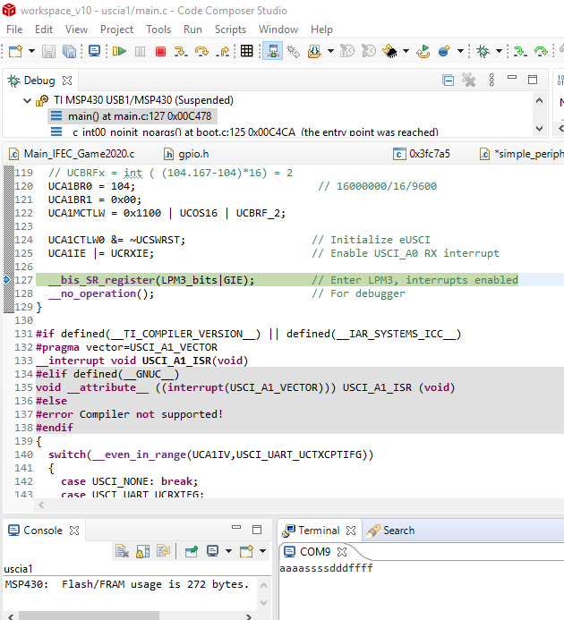
在使用FR2433的串口通讯时,出现串口1无法收发数据,改变端口配置为串口0 时,收发正常。手册中未查到串口A0和A1有差异,程序使用样的配置A1却无法正常收发。
//串口都配置9600bps,目前串口0可以与串口工具进行收发数据,但是串口1接收数据进不到中断里
//串口1发送数据,串口工具也无法接收,用示波器观察单片机端口没有数据。
请TI 帮忙看看,谢谢。
Hi TI team:
在使用FR2433的串口通讯时,出现串口1无法收发数据,改变端口配置为串口0 时,收发正常。手册中未查到串口A0和A1有差异,程序使用样的配置A1却无法正常收发。
//串口都配置9600bps,目前串口0可以与串口工具进行收发数据,但是串口1接收数据进不到中断里
//串口1发送数据,串口工具也无法接收,用示波器观察单片机端口没有数据。
请TI 帮忙看看,谢谢。