This thread has been locked.

If you have a related question, please click the "Ask a related question" button in the top right corner. The newly created question will be automatically linked to this question.

为什么msp430x54xA_adc12_01.c进入不了中断处理程序?

大家好:

     我们购买了M430F5438A几套开发板,希望进行FFT的开发!

    我们将正弦信号接入开发板的P6.7端口,幅值1.2V.

    驱动程序主要的修改如下:

    “   ADC12CTL0 |= ADC12ENC;


        P6SEL |= 0x01;                            // P6.0 ADC option select

        P1DIR |= BIT0;                            // P1.0 output   ”

     修改为:

      “   ADC12CTL0 |= ADC12ENC;


         P6SEL |= = BIT0 + BIT1 + BIT2;                            // P6.7 ADC option select

         P1DIR |= BIT0;                            // P1.0 output  ”

    源程序地址如下:

dev.ti.com/.../node

  • 我会在测试后给您回复
  • 谢谢!
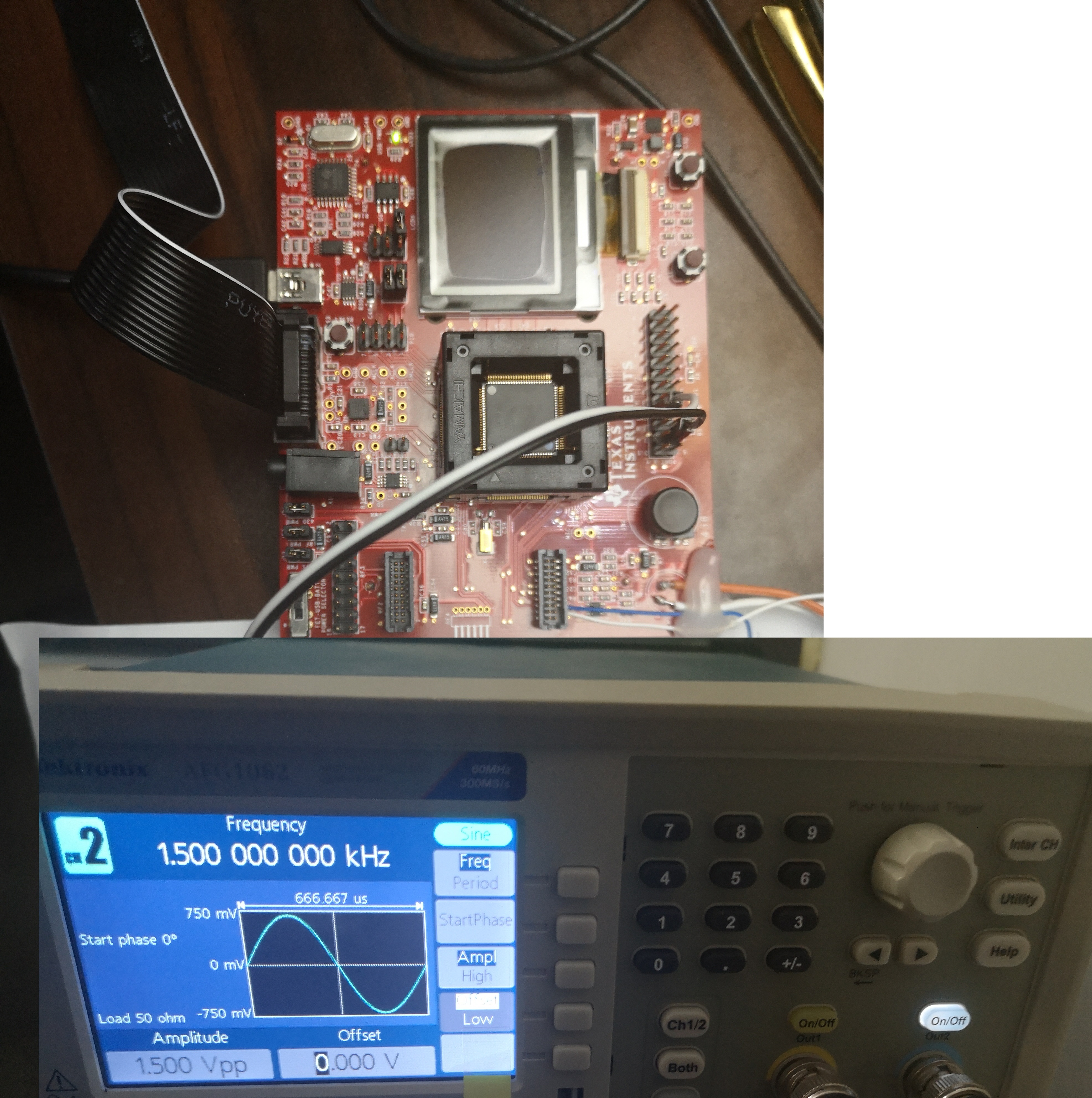
    更新一下,我们采用恒定的正弦信号(频率:1500HZ;幅值MAX=2.24V, 幅值MIN=190mV)
    可以达到0x7ff以上(0.5AVcc)吧?
    我们更关注的是输出数值,还是应当将幅值向上调一些?
  • P6SEL |= = BIT0 + BIT1 + BIT2; // P6.7 ADC option select

    您这个不是P6.7 吧?
  • P6SEL |= 0x80; // P6.0 change to P6.7

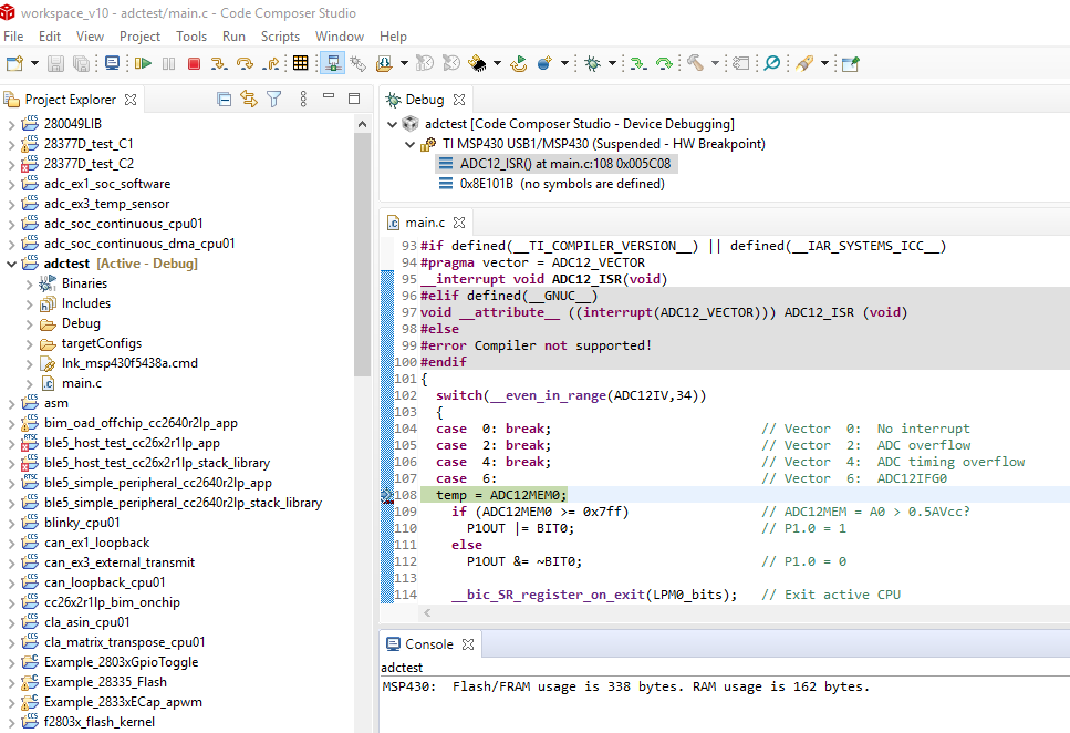
    我试了一下,是可以进入中断服务程序的
  • 抱歉!

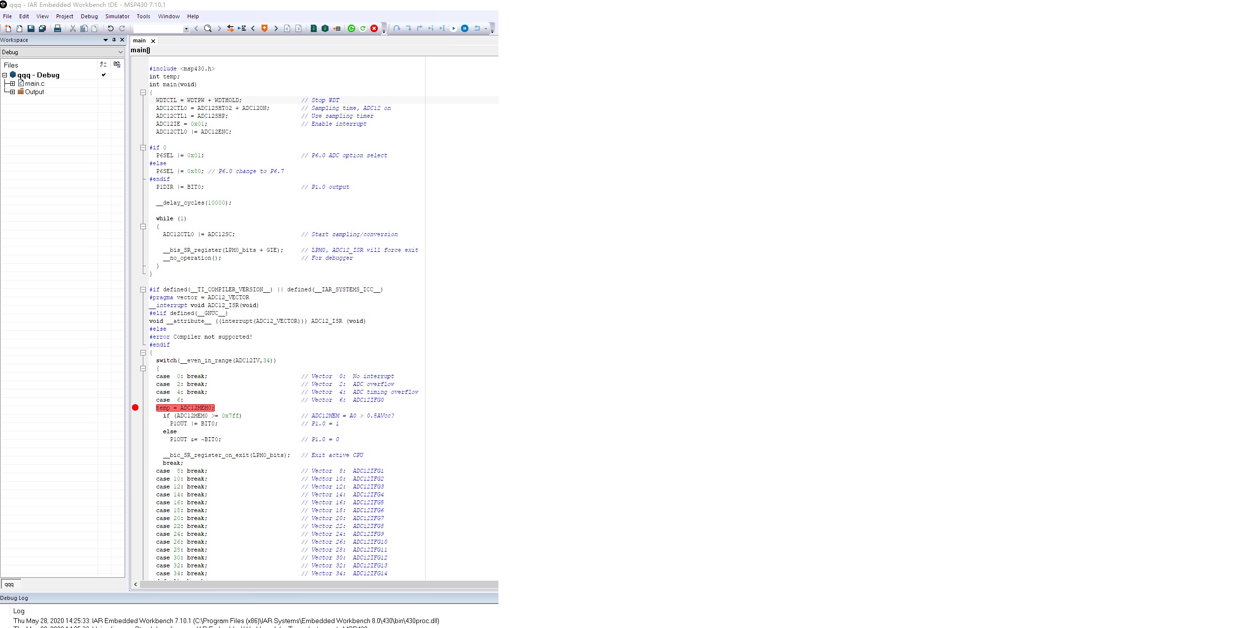
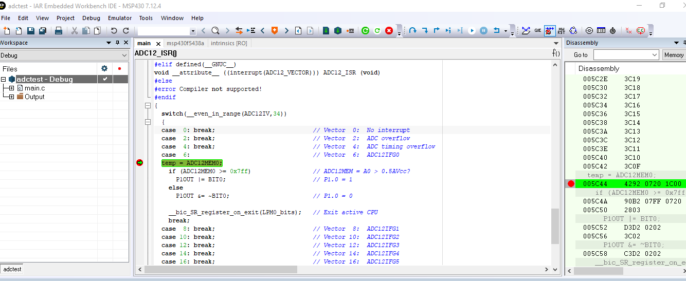
    仍然没有结果!请参考截图

  • 我是使用CCS 10试的,0-2V的正弦波,代码如下

    /* --COPYRIGHT--,BSD_EX
     * Copyright (c) 2012, Texas Instruments Incorporated
     * All rights reserved.
     *
     * Redistribution and use in source and binary forms, with or without
     * modification, are permitted provided that the following conditions
     * are met:
     *
     * *  Redistributions of source code must retain the above copyright
     *    notice, this list of conditions and the following disclaimer.
     *
     * *  Redistributions in binary form must reproduce the above copyright
     *    notice, this list of conditions and the following disclaimer in the
     *    documentation and/or other materials provided with the distribution.
     *
     * *  Neither the name of Texas Instruments Incorporated nor the names of
     *    its contributors may be used to endorse or promote products derived
     *    from this software without specific prior written permission.
     *
     * THIS SOFTWARE IS PROVIDED BY THE COPYRIGHT HOLDERS AND CONTRIBUTORS "AS IS"
     * AND ANY EXPRESS OR IMPLIED WARRANTIES, INCLUDING, BUT NOT LIMITED TO,
     * THE IMPLIED WARRANTIES OF MERCHANTABILITY AND FITNESS FOR A PARTICULAR
     * PURPOSE ARE DISCLAIMED. IN NO EVENT SHALL THE COPYRIGHT OWNER OR
     * CONTRIBUTORS BE LIABLE FOR ANY DIRECT, INDIRECT, INCIDENTAL, SPECIAL,
     * EXEMPLARY, OR CONSEQUENTIAL DAMAGES (INCLUDING, BUT NOT LIMITED TO,
     * PROCUREMENT OF SUBSTITUTE GOODS OR SERVICES; LOSS OF USE, DATA, OR PROFITS;
     * OR BUSINESS INTERRUPTION) HOWEVER CAUSED AND ON ANY THEORY OF LIABILITY,
     * WHETHER IN CONTRACT, STRICT LIABILITY, OR TORT (INCLUDING NEGLIGENCE OR
     * OTHERWISE) ARISING IN ANY WAY OUT OF THE USE OF THIS SOFTWARE,
     * EVEN IF ADVISED OF THE POSSIBILITY OF SUCH DAMAGE.
     *
     *******************************************************************************
     *
     *                       MSP430 CODE EXAMPLE DISCLAIMER
     *
     * MSP430 code examples are self-contained low-level programs that typically
     * demonstrate a single peripheral function or device feature in a highly
     * concise manner. For this the code may rely on the device's power-on default
     * register values and settings such as the clock configuration and care must
     * be taken when combining code from several examples to avoid potential side
     * effects. Also see www.ti.com/grace for a GUI- and www.ti.com/msp430ware
     * for an API functional library-approach to peripheral configuration.
     *
     * --/COPYRIGHT--*/
    //******************************************************************************
    //   MSP430F543xA Demo - ADC12_A, Sample A0, Set P1.0 if A0 > 0.5*AVcc
    //
    //   Description: A single sample is made on A0 with reference to AVcc.
    //   Software sets ADC12SC to start sample and conversion - ADC12SC
    //   automatically cleared at EOC. ADC12 internal oscillator times sample (16x)
    //   and conversion. In mainloop  waits in LPM0 to save power until ADC12
    //   conversion complete, ADC12_ISR will force exit from LPM0 in Mainloop on
    //   reti. If A0 > 0.5*AVcc, P1.0 set, else reset.
    //
    //                MSP430F5438A
    //             -----------------
    //         /|\|                 |
    //          | |                 |
    //          --|RST              |
    //            |                 |
    //     Vin -->|P6.0/A0      P1.0|--> LED
    //
    //   M Morales
    //   Texas Instruments Inc.
    //   June 2009
    //   Built with CCE Version: 3.2.2 and IAR Embedded Workbench Version: 4.2
    //******************************************************************************
    
    #include <msp430.h>
    int temp;
    int main(void)
    {
      WDTCTL = WDTPW + WDTHOLD;                 // Stop WDT
      ADC12CTL0 = ADC12SHT02 + ADC12ON;         // Sampling time, ADC12 on
      ADC12CTL1 = ADC12SHP;                     // Use sampling timer
      ADC12IE = 0x01;                           // Enable interrupt
      ADC12CTL0 |= ADC12ENC;
    
      P6SEL |= 0x80;                            // P6.0 ADC option select P6.7
      P1DIR |= BIT0;                            // P1.0 output
    
      __delay_cycles(10000);
    
      while (1)
      {
        ADC12CTL0 |= ADC12SC;                   // Start sampling/conversion
    
        __bis_SR_register(LPM0_bits + GIE);     // LPM0, ADC12_ISR will force exit
        __no_operation();                       // For debugger
      }
    }
    
    #if defined(__TI_COMPILER_VERSION__) || defined(__IAR_SYSTEMS_ICC__)
    #pragma vector = ADC12_VECTOR
    __interrupt void ADC12_ISR(void)
    #elif defined(__GNUC__)
    void __attribute__ ((interrupt(ADC12_VECTOR))) ADC12_ISR (void)
    #else
    #error Compiler not supported!
    #endif
    {
      switch(__even_in_range(ADC12IV,34))
      {
      case  0: break;                           // Vector  0:  No interrupt
      case  2: break;                           // Vector  2:  ADC overflow
      case  4: break;                           // Vector  4:  ADC timing overflow
      case  6:                                  // Vector  6:  ADC12IFG0
      temp = ADC12MEM0;
        if (ADC12MEM0 >= 0x7ff)                 // ADC12MEM = A0 > 0.5AVcc?
          P1OUT |= BIT0;                        // P1.0 = 1
        else
          P1OUT &= ~BIT0;                       // P1.0 = 0
    
        __bic_SR_register_on_exit(LPM0_bits);   // Exit active CPU
        break;
      case  8: break;                           // Vector  8:  ADC12IFG1
      case 10: break;                           // Vector 10:  ADC12IFG2
      case 12: break;                           // Vector 12:  ADC12IFG3
      case 14: break;                           // Vector 14:  ADC12IFG4
      case 16: break;                           // Vector 16:  ADC12IFG5
      case 18: break;                           // Vector 18:  ADC12IFG6
      case 20: break;                           // Vector 20:  ADC12IFG7
      case 22: break;                           // Vector 22:  ADC12IFG8
      case 24: break;                           // Vector 24:  ADC12IFG9
      case 26: break;                           // Vector 26:  ADC12IFG10
      case 28: break;                           // Vector 28:  ADC12IFG11
      case 30: break;                           // Vector 30:  ADC12IFG12
      case 32: break;                           // Vector 32:  ADC12IFG13
      case 34: break;                           // Vector 34:  ADC12IFG14
      default: break;
      }
    }
    

  • 谢谢!

    请参考我们的环境!

  • 我等下用IAR测试一下

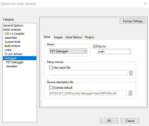
  • 强烈建议使用TI免费的CCS,  请查看您下面的设置

    另外附上调试指南

    http://www.ti.com.cn/cn/lit/ug/zhcu026ac/zhcu026ac.pdf