Other Parts Discussed in Thread: TMP112, MSP430FR2433
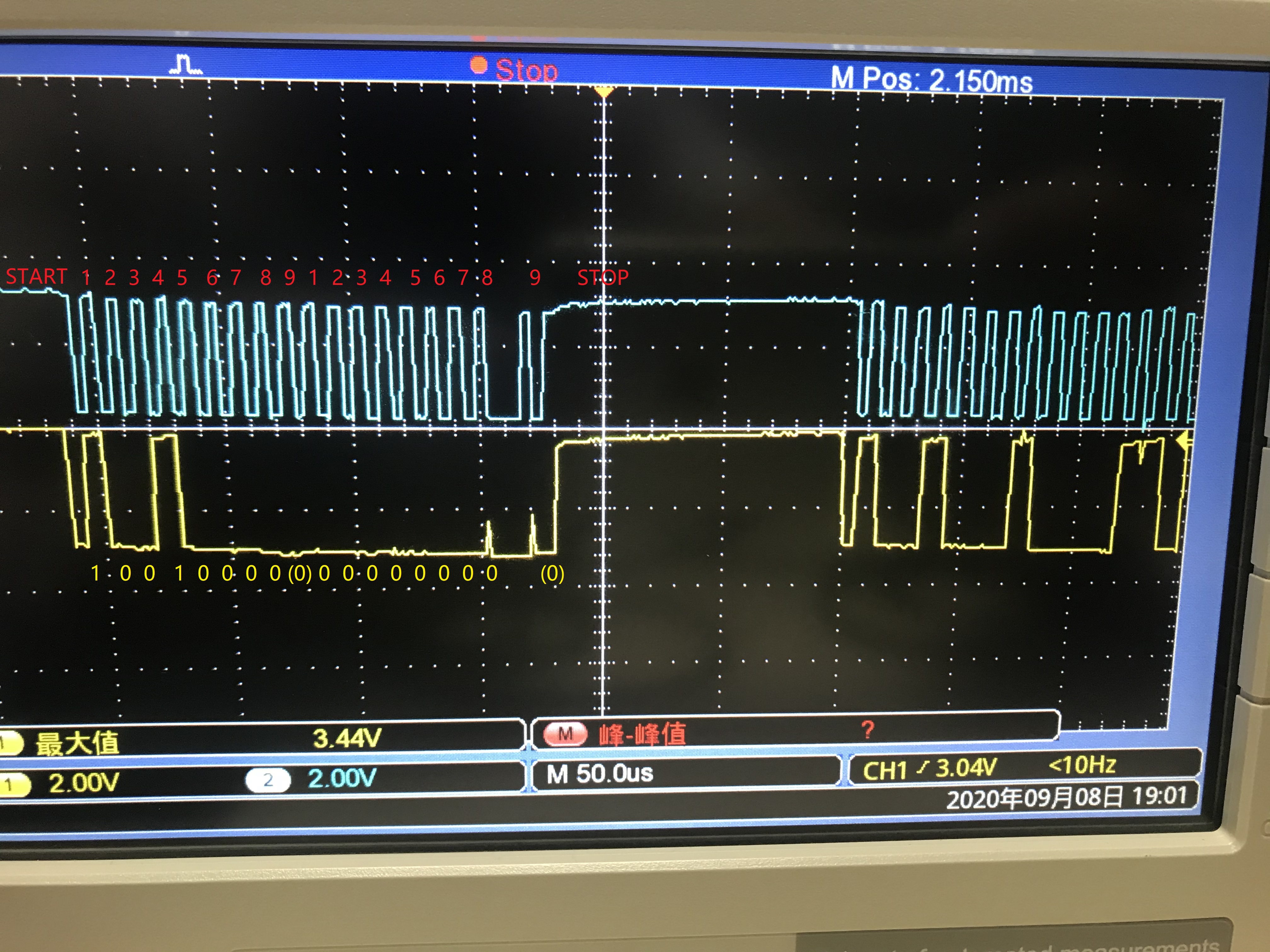
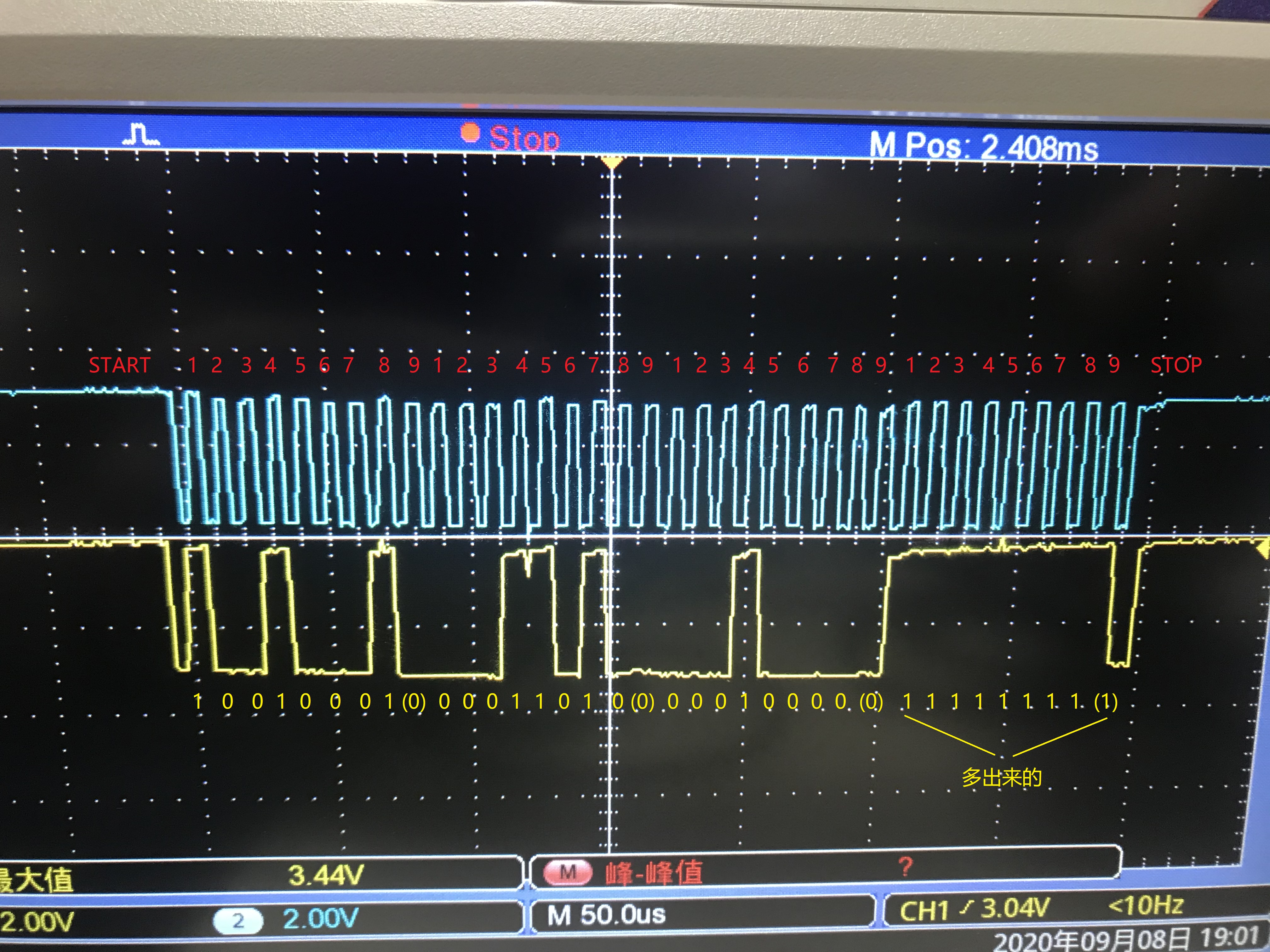
最近用MSP430FR2433+TMP112测试,发现一个很奇怪的问题,在读取TMP112的温度寄存器的2字节数据后,又有9个时钟信号,对应的·SDA一直是高电平,这时UCB0RXBUF里面会变成0xFF,而且必须把这个0xFF给读取出来,否则第二次读取的话发送开始信号后无法进入中断。一直没找到问题所在。
IIC驱动函数如下(参考官方例程):
#include "iic.h"
/* Used to track the state of the software state machine*/
I2C_Mode MasterMode = IDLE_MODE;

/* The Register Address/Command to use*/
uint8_t TransmitRegAddr = 0;

/* ReceiveBuffer: Buffer used to receive data in the ISR
 * RXByteCtr: Number of bytes left to receive
 * ReceiveIndex: The index of the next byte to be received in ReceiveBuffer
 * TransmitBuffer: Buffer used to transmit data in the ISR
 * TXByteCtr: Number of bytes left to transfer
 * TransmitIndex: The index of the next byte to be transmitted in TransmitBuffer
 * */
uint8_t ReceiveBuffer[MAX_BUFFER_SIZE] = {0};
uint8_t RXByteCtr = 0;
uint8_t ReceiveIndex = 0;
uint8_t TransmitBuffer[MAX_BUFFER_SIZE] = {0};
uint8_t TXByteCtr = 0;
uint8_t TransmitIndex = 0;

//******************************************************************************
// Device Initialization *******************************************************
//******************************************************************************

void initI2C()
{
    UCB0CTLW0 = UCSWRST;                      // Enable SW reset
    UCB0CTLW0 |= UCMODE_3 | UCMST | UCSSEL__SMCLK | UCSYNC; // I2C master mode, SMCLK
    UCB0BRW = 0x000A;                         // fSCL = SMCLK/10 = ~100kHz
    UCB0I2CSA = SLAVE_ADDR;                   // Slave Address
    UCB0CTLW0 &= ~UCSWRST;                    // Clear SW reset, resume operation
    UCB0IE |= UCNACKIE;
}

I2C_Mode I2C_Master_ReadReg(uint8_t dev_addr, uint8_t reg_addr, uint8_t count)
{
    /* Initialize state machine */
    MasterMode = TX_REG_ADDRESS_MODE;
    TransmitRegAddr = reg_addr;
    RXByteCtr = count;
    TXByteCtr = 0;
    ReceiveIndex = 0;
    TransmitIndex = 0;

    /* Initialize slave address and interrupts */
    UCB0I2CSA = dev_addr;
    UCB0IFG &= ~(UCTXIFG + UCRXIFG);       // Clear any pending interrupts
    UCB0IE &= ~UCRXIE;                       // Disable RX interrupt
    UCB0IE |= UCTXIE;                        // Enable TX interrupt

    UCB0CTLW0 |= UCTR + UCTXSTT;             // I2C TX, start condition
    __bis_SR_register(LPM0_bits + GIE);              // Enter LPM0 w/ interrupts
    __no_operation();                       // Set breakpoint >>here<< and
    return MasterMode;
}

I2C_Mode I2C_Master_WriteReg(uint8_t dev_addr, uint8_t reg_addr, uint8_t *reg_data, uint8_t count)
{
    /* Initialize state machine */
    MasterMode = TX_REG_ADDRESS_MODE;
    TransmitRegAddr = reg_addr;

    //Copy register data to TransmitBuffer
    CopyArray(reg_data, TransmitBuffer, count);

    TXByteCtr = count;
    RXByteCtr = 0;
    ReceiveIndex = 0;
    TransmitIndex = 0;

    /* Initialize slave address and interrupts */
    UCB0I2CSA = dev_addr;
    UCB0IFG &= ~(UCTXIFG + UCRXIFG);         // Clear any pending interrupts
    UCB0IE &= ~UCRXIE;                       // Disable RX interrupt
    UCB0IE |= UCTXIE;                        // Enable TX interrupt

    UCB0CTLW0 |= UCTR + UCTXSTT;             // I2C TX, start condition
    __bis_SR_register(LPM0_bits + GIE);      // Enter LPM0 w/ interrupts
    __no_operation();                       // Set breakpoint >>here<< and
    return MasterMode;
}

I2C_Mode I2C_Master_ReadData(uint8_t dev_addr, uint8_t count)
{
    /* Initialize state machine */
    MasterMode = RX_DATA_MODE;
    RXByteCtr = count;
    TXByteCtr = 0;
    ReceiveIndex = 0;
    TransmitIndex = 0;

    /* Initialize slave address and interrupts */
    UCB0I2CSA = dev_addr;

    UCB0IFG &= ~(UCTXIFG + UCRXIFG);         // Clear any pending interrupts
    UCB0IE |= UCRXIE;                       // Disable RX interrupt
    UCB0CTLW0 &= ~UCTR;                     // Switch to receiver
    while (UCB0CTL1 & UCTXSTP);             // Ensure stop condition got sent
    UCB0CTLW0 |= UCTXSTT;                   // I2C RX, start condition
    __bis_SR_register(LPM0_bits + GIE);              // Enter LPM0 w/ interrupts
    __no_operation();                       // Set breakpoint >>here<< and
    return MasterMode;
}
void CopyArray(uint8_t *source, uint8_t *dest, uint8_t count)
{
    uint8_t copyIndex = 0;
    for (copyIndex = 0; copyIndex < count; copyIndex++)
    {
        dest[copyIndex] = source[copyIndex];
    }
}

//******************************************************************************
// I2C Interrupt ***************************************************************
//******************************************************************************

#if defined(__TI_COMPILER_VERSION__) || defined(__IAR_SYSTEMS_ICC__)
#pragma vector = USCI_B0_VECTOR
__interrupt void USCI_B0_ISR(void)
#elif defined(__GNUC__)
void __attribute__ ((interrupt(USCI_B0_VECTOR))) USCI_B0_ISR (void)
#else
#error Compiler not supported!
#endif
{
  //Must read from UCB0RXBUF
  uint8_t rx_val = 0;
  switch(__even_in_range(UCB0IV, USCI_I2C_UCBIT9IFG))
  {
    case USCI_NONE:          break;         // Vector 0: No interrupts
    case USCI_I2C_UCALIFG:   break;         // Vector 2: ALIFG
    case USCI_I2C_UCNACKIFG:                // Vector 4: NACKIFG
         UCB0CTL1 |= UCTXSTP;               // I2C start condition
         UCB0IFG = 0;                            // Clear All USCI_B0 flags
         __bic_SR_register_on_exit(LPM0_bits);     // Exit LPM
         MasterMode = NACK_MODE;                // State state is to receive data
      break;
    case USCI_I2C_UCSTTIFG:  break;         // Vector 6: STTIFG
    case USCI_I2C_UCSTPIFG:  break;         // Vector 8: STPIFG
    case USCI_I2C_UCRXIFG3:  break;         // Vector 10: RXIFG3
    case USCI_I2C_UCTXIFG3:  break;         // Vector 12: TXIFG3
    case USCI_I2C_UCRXIFG2:  break;         // Vector 14: RXIFG2
    case USCI_I2C_UCTXIFG2:  break;         // Vector 16: TXIFG2
    case USCI_I2C_UCRXIFG1:  break;         // Vector 18: RXIFG1
    case USCI_I2C_UCTXIFG1:  break;         // Vector 20: TXIFG1
    case USCI_I2C_UCRXIFG0:                 // Vector 22: RXIFG0
        rx_val = UCB0RXBUF;
        if (RXByteCtr)
        {
          ReceiveBuffer[ReceiveIndex++] = rx_val;
          RXByteCtr--;
        }

        if (RXByteCtr == 1)
        {
          UCB0CTLW0 |= UCTXSTP;
        }
        else if (RXByteCtr == 0)
        {
          UCB0IE &= ~UCRXIE;
          //UCB0IFG &=~ UCRXIFG;
          rx_val = UCB0RXBUF;            //这个地方不能注释,要把UCB0RXBUF里面的0xff读出来,不然连续会进不了中断
          MasterMode = IDLE_MODE;
          __bic_SR_register_on_exit(LPM0_bits);      // Exit LPM0
        }
        break;
    case USCI_I2C_UCTXIFG0:                 // Vector 24: TXIFG0
        switch (MasterMode)
        {
          case TX_REG_ADDRESS_MODE:
              UCB0TXBUF = TransmitRegAddr;
              if (RXByteCtr)
                  MasterMode = SWITCH_TO_RX_MODE;   // Need to start receiving now
              else
                  MasterMode = TX_DATA_MODE;        // Continue to transmision with the data in Transmit Buffer
              break;

          case SWITCH_TO_RX_MODE:
              UCB0IE |= UCRXIE;              // Enable RX interrupt
              UCB0IE &= ~UCTXIE;             // Disable TX interrupt
              UCB0CTLW0 &= ~UCTR;            // Switch to receiver
              MasterMode = RX_DATA_MODE;    // State state is to receive data
              UCB0CTLW0 |= UCTXSTT;          // Send repeated start
              if (RXByteCtr == 1)
              {
                  //Must send stop since this is the N-1 byte
                  while((UCB0CTLW0 & UCTXSTT));
                  UCB0CTLW0 |= UCTXSTP;      // Send stop condition
              }
              break;

          case TX_DATA_MODE:
              if (TXByteCtr)
              {
                  UCB0TXBUF = TransmitBuffer[TransmitIndex++];
                  TXByteCtr--;
              }
              else
              {
                  //Done with transmission
                  UCB0CTLW0 |= UCTXSTP;     // Send stop condition
                  MasterMode = IDLE_MODE;
                  UCB0IE &= ~UCTXIE;                       // disable TX interrupt
                  __bic_SR_register_on_exit(LPM0_bits);      // Exit LPM0
              }
              break;

          default:
              __no_operation();
              break;
        }
        break;
    default: break;
  }
}
读取函数如下:
void Tmp102_Read_Temp()
{
I2C_Mode TempMode = IDLE_MODE;
uint8_t reg_data = 0x00;
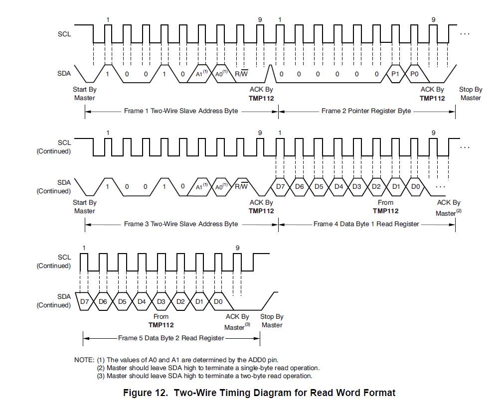
//I2C_Master_ReadReg(TMP102_ADDRESS, Temperature , 2); //也可单独能出结果,但是在发送寄存器地址后没有STOP操作与TMP112时序对不上,查看了TMP117的时序在发送寄存器地址后可以直接RESTART,不用STOP操作
I2C_Master_WriteReg(TMP102_ADDRESS, Temperature, 0 , 0);
I2C_Master_ReadData(TMP102_ADDRESS , 2);
// while(1)
// {
// TempMode = I2C_Master_WriteReg(TMP102_ADDRESS, Temperature, 0 , 0);
// TempMode = I2C_Master_ReadData(TMP102_ADDRESS , 2);
// __delay_cycles(10000);
// }
}