This thread has been locked.
If you have a related question, please click the "Ask a related question" button in the top right corner. The newly created question will be automatically linked to this question.
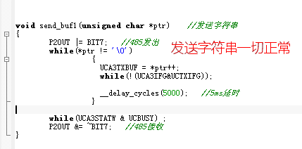
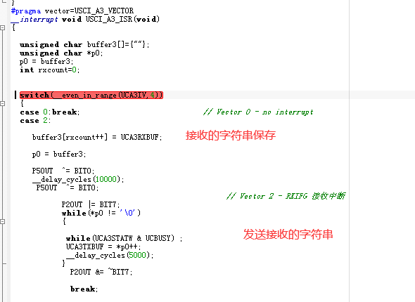
请问在MSP430F6779的UART通信中,UCAxRXBUF能接收的数据是多大,我在实验使用过程中,发现并不能完整接收返回的字符串,只能接收一半。
您好,我是和您提供的帖子采取几乎相同的方式,从串口助手向单片机发送字符串命令,我提高了波特率,发现还是不行。代码如下,不正确的地方麻烦您支持,多谢帮助了~
请您试一下下面的程序,我之前在5529上测试的
示例显示如何配置UCA0 TX和RX中断向量以自动处理字节(字符)接收和发送。收到字节后,它将自动将字节复制到缓冲区。您必须在代码的其他位置设置缓冲区和指针。同样,当您要传输字符串时,请在代码中的某处创建一个缓冲区,并为其分配一个指针。准备好传输字符串时,请启用UCTXIE,ISR将自动处理其余部分。
#include <msp430.h>
#include <stdio.h>
#include <string.h>

//******************************************************************************
// UART Initialization *********************************************************
//******************************************************************************

#define LED_OUT     P1OUT
#define LED_DIR     P1DIR
#define LED_PIN     BIT0

#define SMCLK_115200    0
#define SMCLK_9600      1

#define UART_MODE       SMCLK_115200//SMCLK_9600//

unsigned char RXDataBuffer[64];
unsigned char TXDataBuffer[64] = "Hello world\r\n\0";
unsigned char* pTXBuffer = &TXDataBuffer[0];
unsigned char* pRXBuffer = &RXDataBuffer[0];
unsigned int bytesToSend;
unsigned int bytesReceived;

/*
 * UART timing based on 8MHz SMCLK
 */
void initUART()
{
    // Configure USCI_A0 for UART mode
    UCA0CTLW0 |= UCSWRST;                      // Put eUSCI in reset
#if UART_MODE == SMCLK_115200

    UCA0CTLW0 |= UCSSEL__SMCLK;               // CLK = SMCLK
    // Baud Rate Setting
    // Use Table 21-5
    UCA0BRW = 4;
    UCA0MCTL |= UCOS16 | UCBRF_3 | UCBRS_5;

#elif UART_MODE == SMCLK_9600

    UCA0CTLW |= UCSSEL__SMCLK;               // CLK = SMCLK
    // Baud Rate Setting
    // Use Table 21-5
    UCA0BRW = 52;
    UCA0MCTL |= UCOS16 | UCBRF_1 | UCBRS_0;
#else
    # error "Please specify baud rate to 115200 or 9600"
#endif

    UCA0CTLW0 &= ~UCSWRST;                    // Initialize eUSCI
    UCA0IE |= UCRXIE;                         // Enable USCI_A0 RX interrupt
}

//******************************************************************************
// Device Initialization *******************************************************
//******************************************************************************

void initGPIO()
{
    // Configure GPIO
    P3SEL &= ~(BIT3 | BIT4);                 // USCI_A0 UART operation on FF5529LP
    P3SEL |= (BIT3 | BIT4);
}

void initClockTo16MHz()
{

    UCSCTL3 = SELREF_2;                       // Set DCO FLL reference = REFO
    UCSCTL4 |= SELA_2;                        // Set ACLK = REFO
    UCSCTL0 = 0x0000;                         // Set lowest possible DCOx, MODx

    // Loop until XT1,XT2 & DCO stabilizes - In this case only DCO has to stabilize
    do
    {
    UCSCTL7 &= ~(XT2OFFG + XT1LFOFFG + DCOFFG);
                                            // Clear XT2,XT1,DCO fault flags
    SFRIFG1 &= ~OFIFG;                      // Clear fault flags
    }while (SFRIFG1&OFIFG);                   // Test oscillator fault flag

    __bis_SR_register(SCG0);                  // Disable the FLL control loop
    UCSCTL1 = DCORSEL_5;                      // Select DCO range 16MHz operation
    UCSCTL2 |= 249;                           // Set DCO Multiplier for 8MHz
                                              // (N + 1) * FLLRef = Fdco
                                              // (249 + 1) * 32768 = 8MHz
    __bic_SR_register(SCG0);                  // Enable the FLL control loop

    // Worst-case settling time for the DCO when the DCO range bits have been
    // changed is n x 32 x 32 x f_MCLK / f_FLL_reference. See UCS chapter in 5xx
    // UG for optimization.
    // 32 x 32 x 8 MHz / 32,768 Hz = 250000 = MCLK cycles for DCO to settle
    __delay_cycles(250000);
}

void TransmitData(unsigned char* string, unsigned int length)
{
    pTXBuffer = string;
    bytesToSend = strlen((const char*) string);
    UCA0IE |= UCTXIE;                         // Enable USCI_A0 TX interrupt

}

int main(void)
{
    WDTCTL = WDTPW | WDTHOLD;                               // Stop watchdog timer
    initGPIO();
    initClockTo16MHz();
    initUART();

    /*
    * Use timer to demonstrate automatic tranmission.
    * Configure timer to periodically transmit a string.
    */
    TA0CCTL0 |= CCIE;                                      // TACCR0 interrupt enabled
    TA0CCR0 = 50000;
    TA0CTL |= TASSEL__SMCLK | MC__CONTINUOUS | ID__8;     // SMCLK, continuous mode

    __bis_SR_register(GIE);

    while (1)
    {
        __bis_SR_register(LPM0_bits | GIE);               // Enter LPM0
        __no_operation();                                   // For debugger
    }
}

#pragma vector=USCI_A0_VECTOR
__interrupt void USCI_A0_ISR(void)
{
    switch(__even_in_range(UCA0IV,4))
    {
        case 0: break;
        case 2:
              UCA0IFG &=~ UCRXIFG;              // Clear interrupt
              *pRXBuffer = UCA0RXBUF;             // Clear buffer
              break;
        case 4:
            UCA0TXBUF = *pTXBuffer++;
            if(--bytesToSend == 0)
                UCA0IE &= ~UCTXIE;            // Disable USCI_A0 TX interrupt after string has been transmitted.
            break;
        default:
            break;

    }
    __bic_SR_register_on_exit(LPM0_bits); // Exit LPM0 on reti
}

// Timer A0 interrupt service routine

#pragma vector = TIMER0_A0_VECTOR
__interrupt void Timer_A (void)
{
    static int count = 10;
    if(--count == 0)
    {
        count = 10;
        TransmitData(&TXDataBuffer[0], sizeof(TXDataBuffer));
        _no_operation();

    }
}