Part Number: MSP430FR2433
Other Parts Discussed in Thread: MSP-EXP430FR2433
msp430fr243x_euscia0_spi_09.c (ti.com)
msp430fr243x_euscia0_spi_10.c (ti.com)
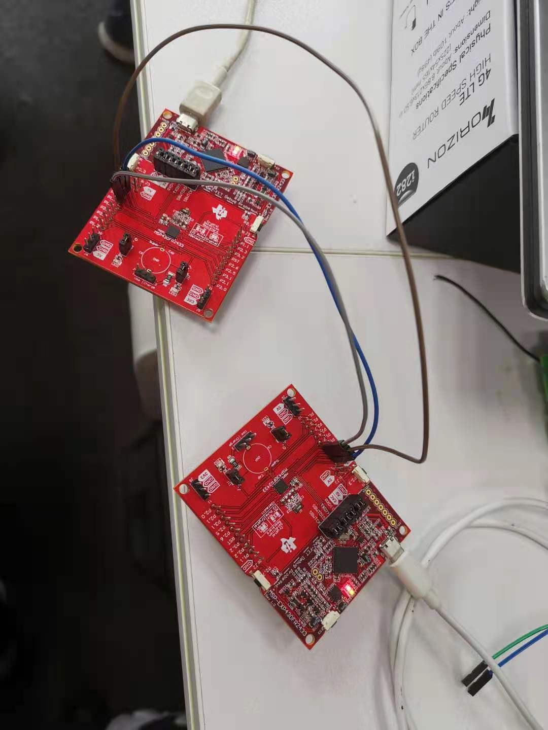
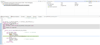
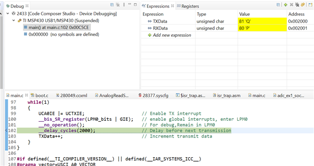
我们使用两个MSP-EXP430FR2433模块测试上述两个示例代码功能,但是在CCS内查看对应参数配置,好像没有数据传输?可以解释一下这两个示例代码吗?我们该怎样查看示例代码是否工作正常?
Part Number: MSP430FR2433
Other Parts Discussed in Thread: MSP-EXP430FR2433
msp430fr243x_euscia0_spi_09.c (ti.com)
msp430fr243x_euscia0_spi_10.c (ti.com)
我们使用两个MSP-EXP430FR2433模块测试上述两个示例代码功能,但是在CCS内查看对应参数配置,好像没有数据传输?可以解释一下这两个示例代码吗?我们该怎样查看示例代码是否工作正常?